background image


c-MIG 2800 / 3300  


5  

EN 

2.4. 

Connecting to the electric network 


Check  if  the  voltage  stated  on  the  device  label  complies  with  rated  voltage  of 
alternate voltage of your electric network.  


The device can be connected to electric socket equipped with protective contact installed by 
authorized electrician. Current circuit of socket must be protected with 16Amp melting safety 
fuse or circuit breaker. 
 

2.5. 

Connecting the MIG/MAG torch 

 
For torch connecting is used EURO Standard torch connector. 
Please, tighten the connector well to eliminate the conduction losses. A loose connection can 
cause damage of the machine and torch. 


Never use damaged torch! 
 
Make sure the contact tip match the manufacturer’s recommendations for type and diameter 
of used wire. Connect the welding conduction main connecting plug into the main socket  on 
the front side. Secure it with the lock nut.  
 
In case Teflon liner is used is it necessary to use contact neck liner out of brass to provide 
good current conduction to the fill wire. 


NOTE: Tighten the screws strongly!  Put the covers back on!  

This is safety-

relevant, the device can’t be used without the covers! 

2.6. 

Selecting the feeding wheel 


Please choose the feeding roll correspond to used welding wire. 
The diameter of the wire is written on appropriate side of the roll (value is in mm).  

Contact pressure adjustment 

Screw plugs 

Wire guide rollers


Содержание c-MIG 2800

Страница 1: ...DE EN Bedienungsanleitung Operating manual REV 1 3 MAHE c MIG 2800 c MIG 3300 ...

Страница 2: ...ällen 9 3 5 Besondere Gefährdung durch Schweißarbeiten 10 4 BEDIENUNG 10 4 1 Einschalten der Maschine 10 4 1 1 Einschaltsequenz auf dem Eingabesystem 10 4 2 Das Fronteingabesystem 11 4 3 Funktionsbeschreibung 11 4 3 1 Betriebsartenschalter 11 4 3 2 Manueller Modus Synergy Modus 12 4 3 3 Drahtgeschwindigkeitseinstellung 12 4 3 4 Zeiteinstellung für Punkt und Intervall Betrieb 12 4 3 5 Einstellung D...

Страница 3: ...r Schweißmaschine 17 8 TECHNISCHE DATEN 18 8 1 C MIG 2800 18 8 2 C MIG 3300 19 9 DURCHSCHNITTLICHE VERBRAUCHSWERTE BEIM SCHWEIßEN 20 9 1 Durchschnittlicher Drahtelektroden Verbrauch beim MIG MAG Schweißen 20 9 1 1 Stahl Drahtelektrode 20 9 1 2 CrNi Drahtelektrode 20 9 1 3 Aluminium Drahtelektrode 20 9 1 4 CuSi Drahtelektrode 20 9 2 Durchschnittlicher Schutzgas Verbrauch beim MIG MAG Schweißen 20 1...

Страница 4: ...ompakt MIG MAG Schweißmaschine der für einen großen Bereich in Industrie Applikationen und Auto Karosseriereparaturen verwendet werden kann Die ausgezeichneten MIG und MIG Löten Charakteristiken ermöglichen der Maschine das Verschweißen von Stahl Edelstahl und bringt sehr gute Ergebnisse beim MIG Löten mit CuSi3 Füllmaterial Beachten Sie bitte die vom Schweiß Prozess ausgehenden Gefährdungen und h...

Страница 5: ...ie Schweißdrahtrolle beigepackt Liste des Zubehörs 1 Schraube M8x16 5 St 9 Gasflaschenplatz 1 St 2 Feder Scheibe M8 5 St 10 Front Versteifung 1 St 3 U Scheibe M8 5 St 11 Front Räder Satz 1 St 4 Schraube M10x40 2 St 12 Hintere Räder 2 St 5 Feder Scheibe M10 2 St 13 Hintere Achse 1 St 6 U Scheibe M10 2 St 14 Gas Anschluss Schlauch 1 St 7 U Scheibe M20 6 St 15 Kette für Gasflasche 2 St 8 Splint 3 5x4...

Страница 6: ...er verwenden Das Drahtkontaktröhrchen muss zu den Hersteller Empfehlungen für den verwendeten Schweißdrahtdurchmesser passen Der Brenner wird an der Frontseite mit dem EURO Anschluss mit der Maschine verbunden Die Mutter muss fest angezogen werden Wird Teflon Schutzschlauch verwendet muss ein Messing Kontaktrohr im Brenner verwendet werden damit ein kleiner Kontakt Widerstand zum Füll Draht herges...

Страница 7: ...erhöhung Herausschrauben Verringerung Während des Einstellens muss das Gerät eingeschaltet sein und der Brennerschalter gedrückt werden damit das Magnetventil geöffnet wird Um unnötigen Drahtverbrauch zu vermeiden ist die Blattfeder des Drahtvorschubs zu öffnen Verwenden Sie immer einen zugelassenen Gasregler für eine Gasflasche Eingriff und Reparaturen an Druckminderen sind wegen der damit verbun...

Страница 8: ...ahlung hat auf ungeschützte Körperstellen sonnenbrandähnliche Wirkungen zur Folge Zum Schutz gegen Funken Wärme sichtbare und unsichtbare Strahlen müssen geeignete Augenschutzmittel Schutzschild oder Schutzhaube mit genormten Strahlenschutzgläsern der Stufen 10 bis 15 nach DIN 4647 je nach Stromstärke getragen werden Nicht mit ungeschützten Augen in den Lichtbogen sehen Gefahr der Blendung und Ver...

Страница 9: ...n die Umgebung der Schweißstelle im Zeitraum von 6 bis 8 Stunden mehrmals nach Glimmstellen Brandnestern Wärmeleitung usw 3 3 Umgang mit Gasflaschen Beim Umgang mit Gasflaschen sind die einschlägigen Sicherheitsvorschriften zu beachten Technische Regeln Druckgase TRG 253 und 303 Insbesondere sind Gasflaschen wegen des gefährlich hohen Innendrucks bis 200 bar gegen mechanische Beschädigung Umfallen...

Страница 10: ...Arbeit und vor dem Wechsel des Standortes des Gerätes ist der Netzstecker zu ziehen Bei Unfällen ist die Schweißstromquelle sofort vom Netz zu trennen Zur Vermeidung von unkontrollierten Schweißrückströmen ist die Schweißleitung mit der Werkstückklemme unmittelbar an das Werkstück fest anzuschließen Keinesfalls dürfen Rohrleitungen Stahlkonstruktionen usw wenn sie nicht das zu schweißende Werkstüc...

Страница 11: ...erfüllen müssen dürfen nur von besonders ausgebildeten und geprüften Schweißern ausgeführt werden Beispielsweise Druckkessel Laufschienen Anhängerkupplungen Fahrzeugrahmen tragende Konstruktionen 4 Bedienung 4 1 Einschalten der Maschine Immer den Hauptschalter der Maschine zum Ein und Ausschalten verwenden niemals den Leistungsstecker im Betrieb ziehen oder stecken 4 1 1 Einschaltsequenz auf dem E...

Страница 12: ...ebsart aus 2 Takt Betrieb 4 Takt Betrieb Draht einführen Gas Test Intervall Betrieb Punkt Betrieb Betriebsarten Drehschalter Drehschalter Manueller Modus Synergy Modus Einstellung Drahtgeschwindigkeit Einstellung Drahtrückbrandzeit Schweißstrom Display Schweißspannung Display Zeiteinstellung für Punkt und Intervall Betrieb ...

Страница 13: ...r Skala von 0 Meter bis 25 Meter eingestellt Im Modus Synergy Schweißen wird der Potentiometer auf die Mittelstellung auf den senkrechten Strich gestellt Feinkorrekturen werden nach links für weniger Draht und nach rechts für mehr Draht eingestellt 4 3 4 Zeiteinstellung für Punkt und Intervall Betrieb Die Intervall Zeiteinstellung von 0 1 Sekunden bis 5 Sekunden erfolgt hier Beachten Sie dass die ...

Страница 14: ...ßspannung erhöht sich mit jeder weiteren Schweißstufe 5 1 1 Tabelle der Lehrlaufspannung für die einzelnen Schweißstufen c MIG 2800 c MIG 3300 Stufe OCV Stufe OCV 1 15 4V 1 15 4V 2 17 2V 2 16 3V 3 18 5V 3 17 3V 4 19 9V 4 18 3V 5 21 5V 5 20 5V 6 23 3V 6 22 2V 7 25 2V 7 23 8V 8 27 9V 8 25 6V 9 30 9V 9 27 9V 10 34 0V 10 30 9V 11 34 3V 12 37 9V 5 2 Drahteinfädelfunktion c MIG Maschinen unterstützen si...

Страница 15: ...us 4 TAKT Modus 2 TAKT 4 TAKT bezieht sich auf die Funktion Brennertasters Die Unterschiede sind in den folgenden beiden Bildern dargestellt t P PWELD t TRIGGER 2 TAKT MIG MAG Betrieb t P t TRIGGER Pre Gas Post Gas 4 TAKT MIG MAG Betrieb ...

Страница 16: ...chrieben vorgenommen werden 25 12 0 6 9 15 18 21 m min 1 3 24 5 4 2 Manuelle Schweißeinstellung Im Modus Handbedienung also bei ausgeschalteter Synergy Funktion wird die Drahtgeschwindigkeit durch den Bediener von 0 Meter bis zu 25 Meter eingestellt Siehe auch Punkt 4 3 3 5 5 Zeitüberwachung kein Lichtbogen Wenn innerhalb von 3s beim Schweißen kein Lichtbogen erkannt wird wird die Stromquelle auto...

Страница 17: ...eißnaht Für die Bewegungsrichtung des Schweißbrenners ergeben sich zwei grundsätzliche Möglichkeiten stechendes Schweißen Brennerbewegung in Richtung Brennerneigung schleppendes Schweißen Brennerbewegung entgegengesetzt zur Brennerneigung Die Auswirkung der Bewegungsrichtung auf die Schweissnaht ist aus nachstehender Tabelle zu ersehen stechendes schleppendes Schweißen Schweißen Einbrandtiefe klei...

Страница 18: ...i Das Vorschubrad die Andruckrolle und die Einlaufdüse sind regelmäßig auf Verschmutzung zu überprüfen und falls notwendig zu reinigen In angemessenen Zeitabständen sollte das komplette Brennerschlauchpaket gereinigt werden weil sich Abrieb und Staub im Inneren absetzen Die Kontaktdüse des Brenners ist ein Verschleißteil Wenn ihre Bohrung zu Groß geworden ist muss sie ausgetauscht werden In den In...

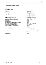
Страница 19: ...80Amp 28V 30 Leerlauf Ausgangsspannung Uo 15 4V 34V Effektivität 73 Leistungsfaktor 0 96 Leistungsaufnahme im Leerlaufzustand 10W Spannungseinstellungsbereich 13 2 29V 10 Stufen Drahtgeschwindigkeitsbereich 0 25 m min Drahtvorschubrollen Durchmesser 37mm Drahtrollendurchmesser 300mm max 17kg max Thermische Klasse H 180 C Temperaturbereiche 10 40 C Betriebstemperatur 40 80 C Lagertemperatur Gehäuse...

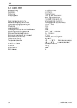
Страница 20: ...V 35 Leerlauf Ausgangsspannung Uo 15 4V 38V Effektivität 73 Leistungsfaktor 0 96 Leistungsaufnahme im Leerlaufzustand 10W Spannungseinstellungsbereich 13 2 33V 12 Stufen Drahtgeschwindigkeitsbereich 0 25 m min Drahtvorschubrollen Durchmesser 37mm Drahtrollendurchmesser 300mm max 17kg max Thermische Klasse H 180 C Temperaturbereiche 10 40 C Betriebstemperatur 40 80 C Lagertemperatur Gehäuse LxWxH 9...

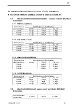
Страница 21: ...rschub Geschwindigkeit Drahtelektroden Durchmesser 0 8 mm 1 0 mm 1 2 mm 3m min 0 9kg h 1 1kg h 1 4kg h 5m min 1 5kg h 1 9kg h 2 3kg h 7m min 2 1kg h 2 7kg h 3 2kg h 9 1 3 Aluminium Drahtelektrode Drahtvorschub Geschwindigkeit Drahtelektroden Durchmesser 0 8 mm 1 0 mm 1 2 mm 3m min 0 4kg h 0 5kg h 5m min 0 7kg h 0 8kg h 7m min 0 9kg h 1 1kg h 9 1 4 CuSi Drahtelektrode Drahtvorschub Geschwindigkeit ...

Страница 22: ...g Verfärbung Mögliche Störung Beseitigung Mögliche Ursache Unruhiger bzw unstabiler Lichtbogen 1 falsche Schweißspannungseinstellung am Spannung korrigieren 2 zu viel wenig Draht am Drahtvorschubsteller regulieren Werkstückklemme lose oder großer guten Kontakt zwischen Werkstück und Übergangswiderstand Rost Farbe Werkstückklemme herstellen 4 Kontaktdüse verschlissen oder auswechseln falscher Durch...

Страница 23: ...schubrad ausgelaufen Vorschubrad wechseln 4 Draht an der Kontaktdüse Kontaktdüse wechseln falls Draht festgebrannt deformiert Anpressdruck verringern Schutzgaszufuhr schaltet nicht ab 1 Magnetventil durch Schmutz am Brenneranschluss und Verbindungsschlauch Schließen gehindert entfernen wechselseitig am Brenner Anschluss und am Verbindungsschlauch Pressluft durchblasen dabei Brenner schalter häufig...

Страница 24: ...23 c MIG 2800 3300 DE Weitere Informationen zu Mahe Produkten erhalten Sie von www mahe online de Die in diesem Handbuch aufgeführten Spezifikationen können ohne vorherige Ankündigung geändert werden ...

Страница 25: ...emoving the fire hazard 8 3 3 Handling the pressure bottles 8 3 4 Protection against electrical accidents 9 3 5 Extraordinary menace during welding 9 4 OPERATION 10 4 1 Turning the device ON 10 4 1 1 Power on sequence 10 4 2 Operating Panel 10 4 3 Functional Description 11 4 3 1 Operating mode selector 11 4 3 2 Synergic selector 11 4 3 3 Wire speed adjustment 12 4 3 4 Cycle Spot welding timer 12 4...

Страница 26: ...isposal of the machine 17 8 TECHNICAL DATA 18 8 1 C MIG 2800 18 8 2 C MIG 3300 19 9 AVERAGE CONSUMPTION VALUES FOR WELDING 20 9 1 Average welding wire consumption for MIG MAG welding 20 9 1 1 Steel welding wire 20 9 1 2 CrNi welding wire 20 9 1 3 Aluminium welding wire 20 9 1 4 CuSi welding wire 20 9 2 Average shielding gas consumption for MIG MAG welding 20 10 TROUBLESHOOTING 21 ...

Страница 27: ... is a compact MIG MAG welding machine that can be used for a wide range of industrial applications and car body repairs The excellent MIG and MIG soldering characteristics enable the machine to weld steel stainless steel and bring very good results when MIG soldering with CuSi3 filler material Be aware of danger resulted from welding and follow the safety and fire instructions 2 PUTTING INTO OPERA...

Страница 28: ...g area List of accessories 1 Screw M8x16 5 St 9 Gas bottle base 1 St 2 Split lock washer M8 5 St 10 Front stiffener 1 St 3 Straight washer M8 5 St 11 Wheel set front 1 St 4 Screw M10x40 2 St 12 Wheel set rear 2 St 5 Split lock washer M10 2 St 13 Rear axle 1 St 6 Straight washer M10 2 St 14 Gas hose 1 St 7 Straight washer M20 6 St 15 Fixing chain 2 St 8 Split pin 3 5x40 2 St 2 3 Assembly of accesso...

Страница 29: ...ause damage of the machine and torch Never use damaged torch Make sure the contact tip match the manufacturer s recommendations for type and diameter of used wire Connect the welding conduction main connecting plug into the main socket on the front side Secure it with the lock nut In case Teflon liner is used is it necessary to use contact neck liner out of brass to provide good current conduction...

Страница 30: ... If you use an adjustable reduction valve you can adjust a gas flow with a wing nut with a litre scale The device must be turned on and Gas check function activated the welding button must be pressed during adjustment Always use an approved gas regulator for a gas bottle It is not allowed to repair pressure regulators It is necessary to send the defective regulators to service 2 8 Connecting the r...

Страница 31: ...to wear an appropriate eye protection against sparks heat visible and invi sible radiation protective shield or protective helmet equipped with protective glass from the 10 th to 15 th grade according to DIN 4647 standard depending on used current Do not look into an electric arc with unprotected eyes you can go blind or you can burn Invisible U V radiation causes a very painful eye conjunctiva in...

Страница 32: ... of welding check up the welding place for smoking parts or small fires in the time interval up to 6 or 8 hours 3 3 Handling the pressure bottles You have to follow respective safety regulations technical regulations for pressure gas TRG 253 and 303 Due to high pressure inside the bottles up to 200 bar it is necessary to secure them against mechanical damage overturning downfall heating up max 50 ...

Страница 33: ...nductive connection with protective or zero con ductor of the power supply network Because the protective contact of power supply is con nected to welding device you must not put the grounding clamp down on the welding device body when the device is connected to power supply network The workpiece must be insulated from power supply protective and zero conductor and from the grounding con ductor 3 ...

Страница 34: ...ating panel to give the user information about the firmware a Firmware type in voltage window Fm Front panel IM b A mperage rating in Ampere window 200 200Amp c Firmware revision in Ampere window r11 major minor revision numbers 4 2 Operating Panel Operating modes Switch Switch for manual mode synergy mode Wire Speed setting Welding current display Welding voltage display Setting the wire Burn bac...

Страница 35: ...our cycle operation manual feed of wire gas test cycle welding mode spot welding mode 4 3 2 Synergic selector Manual mode synergic functionality is off 0 8 wire SG2 SG4 0 8mm diameter shielding gas 82 Ar 18 CO2 1 0 wire SG2 SG4 1 0mm diameter shielding gas 82 Ar 18 CO2 1 2 wire SG2 SG4 1 2mm diameter shielding gas 82 Ar 18 CO2 ...

Страница 36: ...up welding time for cycle and spot welding The idle time for cycle welding is always equal to welding time Adjustment range is 0 1sec to 5sec 4 3 5 Burn back adjustment Length of the outstanding wire after the weld setup 4 4 Welding current voltage display Machines are equipped with real welding voltage and current display with implemented HOLD function Display is measuring and displaying welding ...

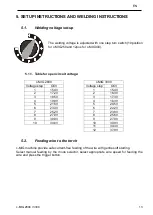
Страница 37: ...300 Voltage step OCV Voltage step OCV 1 15 4V 1 15 4V 2 17 2V 2 16 3V 3 18 5V 3 17 3V 4 19 9V 4 18 3V 5 21 5V 5 20 5V 6 23 3V 6 22 2V 7 25 2V 7 23 8V 8 27 9V 8 25 6V 9 30 9V 9 27 9V 10 34 0V 10 30 9V 11 34 3V 12 37 9V 5 2 Feeding wire to the torch c MIG machine provide safe current free feeding of the wire with gentle soft starting Select manual feeding by the mode selector select appropriate wire...

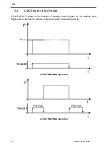
Страница 38: ...T 4 TACT relates to the function of starting button trigger on the welding torch Differences in operation of this two modes are shown in following pictures t P PWELD t TRIGGER 2 TACT MIG MAG operation t P t TRIGGER Pre Gas Post Gas 4 TACT MIG MAG operation ...

Страница 39: ... value is possible 25 12 0 6 9 15 18 21 m min 1 3 24 5 4 2 Manual mode operation To disable automatic preset of wire speed manual mode should be selected by Synergyc elector In this case user can set up wire speed direct by wire speed potentiometer according printed scale in range 0 25m min 5 5 NO ARC timeout If there is no arc detected for more than 3 seconds during active welding the welding pro...

Страница 40: ...o basic possibilities concerning to movement direction of the torch welding against weld direction moving in direction of the torch declination welding in weld direction moving against direction of the torch declination The effect of the movement you can see in the following table welding against weld direction welding in weld direction Depth of burn less more Weld width more less Weld surface ruf...

Страница 41: ...e is not some dirt If it is you have to clean it out Please change the contact tip on the torch regulary The complete set of pressure hoses should be cleaned up from time to time because of em bedded dust and parts The contact nozzle of the torch is wearing up subsequently When the hole in the nozzle is too large it is necessary to change the nozzle The metal drops are embedding in the inner walls...

Страница 42: ...um input current I1eff 8 2Amp 280Amp 28V 30 No load output voltage Uo 15 4V 34V Efficiency 76 Power factor 0 96 No load power consumption 10W Voltage adjustment range 13 2 29V 10 steps Wire speed range 0 25 m min Wire feed roll diameter 37mm Wire spool diameter 300mm max 17kg max Thermal class H 180 C Temperature range 10 40 C operating temp 40 80 C storage temp Dimensions LxWxH 900x500x840mm Weig...

Страница 43: ...mp 30 5V 35 No load output voltage Uo 15 4 38V Efficiency 76 Power factor 0 96 No load power consumption 10W Voltage adjustment range 13 2 33V 12 steps Wire speed range 0 25 m min Wire feed roll diameter 37mm Wire spool diameter 300mm max 17kg max Thermal class H 180 C Temperature range 10 40 C operating temp 40 80 C storage temp Dimensions LxWxH 900x500x840mm Weight 72kg Degree of protection IP23...

Страница 44: ... 2 mm 3m min 0 9kg h 1 1kg h 1 4kg h 5m min 1 5kg h 1 9kg h 2 3kg h 7m min 2 1kg h 2 7kg h 3 2kg h 9 1 3 Aluminium welding wire Wire feed rate Welding wire diameter 0 8 mm 1 0 mm 1 2 mm 3m min 0 4kg h 0 5kg h 5m min 0 7kg h 0 8kg h 7m min 0 9kg h 1 1kg h 9 1 4 CuSi welding wire Wire feed rate Welding wire diameter 0 8 mm 1 0 mm 1 2 mm 3m min 1kg h 1 2kg h 1 4kg h 5m min 1 6kg h 2kg h 2 4kg h 7m mi...

Страница 45: ...he voltage 2 too much little wire adjust the wire feed regulator 3 The workpiece clamp is loose make a good contact between workpiece or transfer resistance is too high rust and clamp paint 4 The contact nozzle is worn up or change it the diameter is wrong 5 The gas flow is not correct adjust the gas flow 6 The workpiece is not clear in the welding remove paint rust fat etc area 7 Performance grad...

Страница 46: ...wire is deformed lower the pressure on wire Device turns OFF and the Err t is displayed 1 Time of make is exceeded TM Let the device cool down and follow the instructions for TM according to device type The protective gas still flows 1 Magnetic valve is dirty and it is still open Disconnect the torch connector and connecting hose alternately flow a pressure air into the torch connector and connect...

Страница 47: ...c MIG 2800 3300 23 EN Further information about MAHE products are available on www mahe online de The specifications listed in this manual are subject to change without notice ...

Страница 48: ...Mahe GmbH Auwiese 12 57223 Kreuztal GERMANY www mahe online de MAHE ...

Отзывы: