TWIN F 3.0 A / TWIN F 3.0 U
D1 5002BA1-GB01
25
7 CHAPTER 7 - INSTALLATION
!!!!
ONLY SKILLED TECHNICIAN
,
APPOINTED BY THE MANUFACTURER
,
OR BY
AUTHORISED DEALERS
,
MUST BE ALLOWED TO CARRY OUT THESE
OPERATIONS
.
SERIOUS DAMAGE TO PEOPLE AND THE LIFT CAN BE CAUSED IF
THEY ARE MADE BY OTHER PERSONS
.
BEFORE CARRYING OUT ANY OPERATIONS
,
REMEMBER TO INSERT THE SAFETY
PIECE OF WOOD BETWEEN THE LOWER BOOMS AND THE BASE FRAME
(R
EF
.
F
IGURE
15)
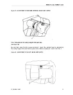
Figure 15 - SAFETY BLOCK
7.1 Preliminary
operations
CHECKING FOR ROOM SUITABILITY
The lift has been designed to be used in covered and sheltered places.
The place of installation must not be next to washing areas, painting workbenches,
solvent or varnish deposits; the installation near to rooms where a dangerous situation
of explosion can occur is strictly forbidden. The relevant standards of the local Health
and Safety at Work regulations, for instance with respect to minimum distance to wall or
other equipment, escapes and the like, shall be observed.
LIGHTING
Lighting must be carried out according to the effective regulations of the place of
installation. All areas next to the lift must be well and uniformly lit.
Содержание Twin Series
Страница 4: ...TWIN F 3 0 A TWIN F 3 0 U D1 5002BA1 GB01 II ...
Страница 6: ...TWIN F 3 0 A TWIN F 3 0 U D1 5002BA1 GB01 IV ...
Страница 8: ...TWIN F 3 0 A TWIN F 3 0 U D1 5002BA1 GB01 VI ...
Страница 10: ...TWIN F 3 0 A TWIN F 3 0 U D1 5002BA1 GB01 VIII ...
Страница 14: ...TWIN F 3 0 A TWIN F 3 0 U D1 5002BA1 GB01 4 ...
Страница 19: ...TWIN F 3 0 A TWIN F 3 0 U D1 5002BA1 GB01 9 Figure 2 LIFT ...
Страница 21: ...TWIN F 3 0 A TWIN F 3 0 U D1 5002BA1 GB01 11 Figure 3 CONTROL DESK ...
Страница 34: ...TWIN F 3 0 A TWIN F 3 0 U D1 5002BA1 GB01 24 ...
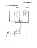
Страница 37: ...TWIN F 3 0 A TWIN F 3 0 U D1 5002BA1 GB01 27 Figure 16 HYDRAULIC PIPES CONNECTION Platform 1 Platform 2 ...
Страница 45: ...TWIN F 3 0 A TWIN F 3 0 U D1 5002BA1 GB01 35 ...
Страница 46: ...TWIN F 3 0 A TWIN F 3 0 U D1 5002BA1 GB01 36 ...
Страница 51: ......

