TWIN F 3.0 A / TWIN F 3.0 U
D1 5002BA1-GB01
20
6.1 General
warnings
The operator and the person in charge of maintenance must follow accident-prevention
laws and rules in force in the country where the lift is installed.
They also must carry out the following:
•
neither remove nor disconnect hydraulic, electric or other safety devices;
•
carefully follow the safety indications applied on the machine and included in
the manual;
•
observe the safety area during lifting;
•
be sure the motor of the vehicle is off, the gear engaged and the parking brake
put on;
•
be sure only authorised vehicles are lifted without exceeding the maximum
lifting capacity;
•
verify that no one is on the platforms during lifting or standing
6.2 Risks during vehicle lifting
To avoid overloading and possible breaking, the following safety devices have been
used:
•
a maximum pressure valve placed inside the hydraulic unit to prevent
excessive weight
•
a special design of the hydraulic system, in case of pipeline failure, to prevent
sudden lift lowering
6.3 Risks for people
All risks the personnel could run, due to an improper use of the lift, are described in this
section.
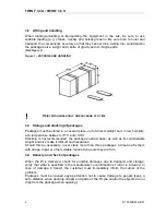
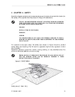
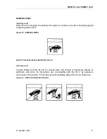
PERSONNEL CRUSHING RISKS
(Ref. Figure 9)
During lowering of runways and vehicles, personnel must not be within the area
covered by the lowering trajectory. The operator must be sure no one is in danger
before operating the lift.
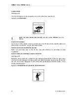
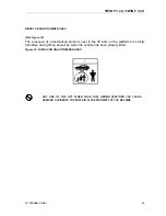
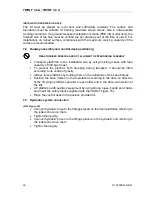
Figure 9 – CRUSHING RISKS
Содержание Twin Series
Страница 4: ...TWIN F 3 0 A TWIN F 3 0 U D1 5002BA1 GB01 II ...
Страница 6: ...TWIN F 3 0 A TWIN F 3 0 U D1 5002BA1 GB01 IV ...
Страница 8: ...TWIN F 3 0 A TWIN F 3 0 U D1 5002BA1 GB01 VI ...
Страница 10: ...TWIN F 3 0 A TWIN F 3 0 U D1 5002BA1 GB01 VIII ...
Страница 14: ...TWIN F 3 0 A TWIN F 3 0 U D1 5002BA1 GB01 4 ...
Страница 19: ...TWIN F 3 0 A TWIN F 3 0 U D1 5002BA1 GB01 9 Figure 2 LIFT ...
Страница 21: ...TWIN F 3 0 A TWIN F 3 0 U D1 5002BA1 GB01 11 Figure 3 CONTROL DESK ...
Страница 34: ...TWIN F 3 0 A TWIN F 3 0 U D1 5002BA1 GB01 24 ...
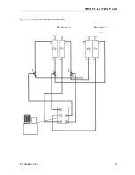
Страница 37: ...TWIN F 3 0 A TWIN F 3 0 U D1 5002BA1 GB01 27 Figure 16 HYDRAULIC PIPES CONNECTION Platform 1 Platform 2 ...
Страница 45: ...TWIN F 3 0 A TWIN F 3 0 U D1 5002BA1 GB01 35 ...
Страница 46: ...TWIN F 3 0 A TWIN F 3 0 U D1 5002BA1 GB01 36 ...
Страница 51: ......

