©
2013 Magnum Energy, Inc.
Page 20
Installation
2.5.4
AC Terminal Block Connections
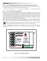
The inverter has a six-pole AC terminal block and two AC ground terminals to connect the inverter’s
AC input and output wiring. The MSH-RE Series provides a terminal block (see Figure 2-8) that
allows the AC input and output wiring to be permanently wired. This terminal block allows either
a service/distribution panel (main panel) or a generator to be wired to the inverter’s input, and
then to a dedicated panel (sub-panel) between the inverter’s output wiring and the AC loads. To
access and view the AC terminal block and ground terminal, remove the two Phillips screws holding
the AC wiring access cover plate (see Item 15, Figure 1-3).
Each connection on the AC terminal block is rated for 105°C and can accept one #18 to #2 AWG
(0.82 to 33.6 mm
2
) CU stranded wire; or two #14 to #8 AWG (2.1 to 8.7 mm
2
) CU stranded wires.
Each connection uses a 1/4-28 screw and the maximum tightening torque is 32 in lbf (3.6 Nm).
Info
: The inverter’s NEUTRAL IN and NEUTRAL OUT terminals are electrically connected
to each other and either connection can be for the input or output neutrals.
The AC ground terminals can accept one #14 to #6 AWG (2.1 to 13 mm
2
) CU stranded wire each.
They use a slotted head screw and have a recommended maximum tightening torque of 45 in lbf
(5.1 N-m).
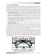
Figure 2-8, AC Terminal Block
WARNING:
HIGH
VOLTAGE
“Use Copper
Conductors
Only”
See manual
for specific wire
sizes and types.
120VAC Input/Output Only
HOT OUT
NEUTRAL
IN/OUT
GRID IN (AC1)
GEN IN (AC2)
AC
GROUNDS
2.5.3
Recommended GFCI (Ground Fault Circuit Interruption) Outlets
In compliance with UL standards, Magnum Energy has tested the following GFCIs and
fi
nd that
they function properly when connected to the inverter’s AC output:
• Shock
Sentry
TM
#XGF15V-SP
• Leviton Smart Lock #8899-A • Hubbel
#GF520EMBKA


