background image

 3

Set-Up (cont’d)

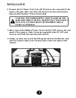
 5. Next, connect the Monitor Power Cord 

 on the rear 

     panel of the camera.  Note: the power supplied to the AC OUT jack 
     turns on & off with the camera power switch. 

to the AC OUT jack

 6. Finally, connect one end of the DVI signal cable to the Monitor Jack 
     and the Control Cable to the Control Jack on the rear panel of the
     camera.

4. Connect the AC Power Cord to the AC IN jack on the rear panel of the 
    camera. Plug the other end of the AC Power Cord into wall outlet or 
    surge protected power strip (not included).

!

CAUTION: THE POWER SUPPLY CORD IS USED AS THE 
MAIN DISCONNECT DEVICE. ENSURE THAT THE SOCKET-
OUTLET IS LOCATED NEAR THE EQUIPMENT AND IS 
EASILY ACCESSIBLE

DVI Signal Cable 

Control Cable 

Power Cord (to Wall Outlet)

Monitor 
Power Cord 

Содержание Explorer MSE-L22-HD

Страница 1: ...MSE L22 HD User s Manual R Model A...

Страница 2: ...found to comply with the limits for a Class B digital device pursuant to part 15 of the FCC Rules These limits are designed to provide reasonable protection against harmful interference when the equi...

Страница 3: ...near any heat source or direct sunlight P Camera unit on the desk surface to your preferred location The bottom of the unit is equipped with rubber pads to protect the table surface and to prevent th...

Страница 4: ...trol Cable to the Control Jack on the rear panel of the camera 4 Connect the AC Power Cord to the AC IN jack on the rear panel of the camera Plug the other end of the AC Power Cord into wall outlet or...

Страница 5: ...t corner of the Monitor below the screen The Monitor settings are set at the recommended settings so there is not need to adjust the monitor settings Place text or your hand under the camera to confir...

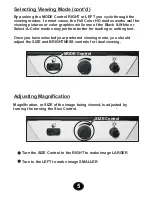
Страница 6: ...better for reading or writing text Once you have selected your preferred viewing mode you should adjust the SIZE and BRIGHTNESS controls for ideal viewing Selecting Viewing Mode cont d 5 Magnification...

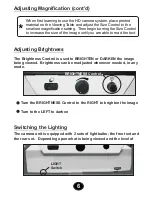
Страница 7: ...o use the HD camera system place printed material on the Viewing Table and adjust the Size Control to the smallest magnification setting Then begin turning the Size Control to increase the size of the...

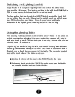
Страница 8: ...he LIGHT Switch under the front left corner of the Camera unit Changing the switch position will change turn ON the front or rear lights Once the preferred setting is determined the lighting can norma...

Страница 9: ...the table allows you to line up pages or envelopes This is especially useful for writing 2 Non glare wipeable table surface reduces eyestrain Its dark color and speckled pattern helps you to distingu...

Страница 10: ...s recommended to protect your unit from power outages etc 4 Avoid putting your hands and fingers into any opening touching the camera lens or mirror in the camera housing could reduce image quality 5...

Страница 11: ...e is required you may be asked to send the unit to MagniSight s main repair facility The camera or system MUST BE SHIPPED IN THE ORIGINAL PACKAGING to prevent damage Please call MagniSight for return...

Отзывы: