6
46-620 B73 & Series 75 Liquid Level Switches
5b. Close shut-off valves (if so equipped) to isolate control
from tank. Drain off liquid in float chamber.
5c. On installations without shut-off valves, relieve pressure
from the tank. Drain liquid in tank to a level below the
connections of the float chamber.
NOTE: Level control, connections and pipe lines need not be
removed from the tank.
6. Loosen enclosing tube nut with a
15
⁄
16
" wrench. Unscrew
enclosing tube counterclockwise (switch and housing base
will rotate also), until it is free. Refer to
Figure 8
.
7. Lift enclosing tube, switch, and base off float chamber.
Jam nuts and attraction sleeve are now accessible.
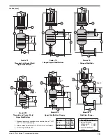
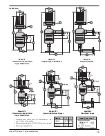
8. Measure the distance “D” from the top edge of the upper
jam nuts to the top of the float stem. Refer to
Figure 7
.
Record this measurement.
9. Loosen and remove upper jam nuts, guide washer and
attraction sleeve.
10. Loosen and adjust lower jam nuts to the desired position.
Tighten lower jam nuts securely. Refer to
Figure 7
.
11. Replace attraction sleeve on stem.
12. Replace upper jam nuts and guide washer on the stem in
the position previously noted. Tighten upper jam nuts
securely. Refer to
Figure 7
.
NOTE: Use a new enclosing tube gasket when reassembling enclos-
ing tube to the chamber. Make certain that all gasket surfaces
are thoroughly cleaned to allow proper gasket seating. Coat
enclosing tube threads with anti-seizing compound.
13. Replace enclosing tube, switch, and base on chamber. Screw
tube clockwise until tightened to 75–100 foot-pounds of
torque for a fiber gasket or 200–225 foot-pounds
of torque for a spiral wound gasket.
14. Loosen the set screws at the base of the switch housing.
Rotate switch housing to correct position and tighten set
screws. Refer to
Figure 2
on page 3.
15. Bring supply wires through conduit outlet. Follow steps
5 through 10 in
Section 1.5, Wiring
on page 3.
16. Test switch action by varying liquid level in float chamber.
NOTE: If switch mechanism fails to function properly, check vertical
alignment of control housing and consult installation bulletin
on switch mechanism. If the unit still fails to function properly,
consult the factory.
Float
Enclosing tube
Refer to Figures 6 and 7
Housing base
Enclosing tube nut
Conduit
connection
Switch housing
cover
Chamber
Figure 8


