


8
45-610 Displacer Type Liquid Level Switches and Proof-er
®
Switches
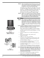
INTERNAL
CIRCUIT
4
5
6
LOAD
Close on low level (NC)
COMMON (C)
Close on high level (NO)
LINE
LOAD
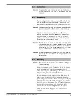
NOTES:
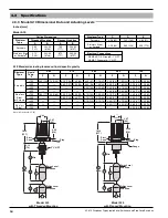
1. Rising level closes contacts 5 & 6.
2. Falling level closes contacts 4 & 5.
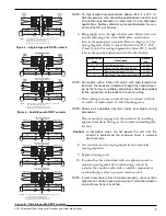
INTERNAL
CIRCUIT
1
2
3
L
O
A
D
C
lose
on
low
level
(
NC
)
C
O
MM
O
N
(
C
)
C
lose
on
high
level
(
N
O
)
LINE
L
O
A
D
N
O
TE
S:
1. Rising level closes contacts 5 & 6 and 2 & 3.
2. Falling level closes contacts 4 & 5 and 1 & 2.
A
SS
E
M
.
A
Upper Level Range Operates
Upper Switch Mechanism
INTERNAL
CIRCUIT
4
5
6
L
O
A
D
C
lose
on
low
level
(
NC
)
C
O
MM
O
N
(
C
)
C
lose
on
high
level
(
N
O
)
LINE
L
O
A
D
A
SS
E
M
.
B
Lower Level Range Operates
Lower Switch Mechanism
INTERNAL
CIRCUIT
1
2
3
L
O
A
D
C
lose
on
low
level
(
NC
)
C
O
MM
O
N
(
C
)
C
lose
on
high
level
(
N
O
)
LINE
L
O
A
D
N
O
TE
S:
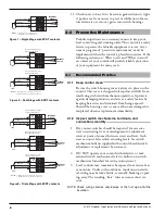
1. Rising level closes contacts 5 & 6 and 2 & 3.
2. Falling level closes contacts 4 & 5 and 1 & 2.
A
SS
E
M
.
A
A
SS
E
M
.
B
Upper Level Range Operates
Upper Switch Mechanism
Middle Level Range Operates
Middle Switch Mechanism
INTERNAL
CIRCUIT
4
5
6
L
O
A
D
C
lose
on
low
level
(
NC
)
C
O
MM
O
N
(
C
)
C
lose
on
high
level
(
N
O
)
LINE
L
O
A
D
A
SS
E
M
.
B
Lower Level Range Operates
Lower Switch Mechanism
INTERNAL
CIRCUIT
4
5
6
L
O
A
D
C
lose
on
low
level
(
NC
)
C
O
MM
O
N
(
C
)
C
lose
on
high
level
(
N
O
)
LINE
L
O
A
D
Figure 7 – Single Stage with SPDT contacts
Figure 8 – Dual Stage with SPDT contacts
Figure 9 – Triple Stage with SPDT contacts
11. Check cover to base fit to be certain gasketed joint is tight.
A positive seal is necessary to prevent infiltration of mois-
ture laden air or corrosive gasses into switch housings.
3.0
Preventive Maintenance
Periodic inspections are a necessary means to keep your
level control in good working order. This control is a safety
device to protect the valuable equipment it serves. A sys-
tematic program of “preventive maintenance” must be
implemented when the control is placed into service. If the
following sections on “What to do” and “What to avoid”
are observed, your control will provide reliable protection
of your equipment for many years.
3.1
Recommended Practice
3.1.1 Keep control clean
Be sure the switch housing cover is always in place on the
control. This cover is designed to keep dust and dirt from
interfering with switch mechanism operation. It protects
against damaging moisture and acts as a safety feature by
keeping bare wires and terminals from being exposed.
Should the housing cover or any seal become damaged or
misplaced, obtain a replacement immediately.
3.1.2 Inspect switch mechanisms, terminals, and
connections monthly
1. Dry contact switches should be inspected for excessive
wear on actuating lever or misalignment of adjustment
screw at point of contact between screw and lever. Such
wear can cause false switch actuating levels. See switch
mechanism bulletin supplied with control should switch
adjustment or replacement be necessary.
2. DO NOT operate your control with defective or mal-
adjusted switch mechanisms (refer to bulletin on switch
mechanisms furnished for service instructions.)
3. Level controls may sometimes be exposed to excessive heat
or moisture. Under such conditions, insulation on electri-
cal wiring may become brittle, eventually breaking or peal-
ing away. The resulting “bare” wires can cause short cir-
cuits.
NOTE: Check wiring carefully and replace at the first sign of brittle
insulation.


