


6
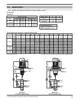
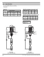
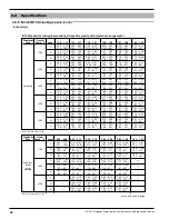
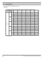
45-610 Displacer Type Liquid Level Switches and Proof-er
®
Switches
Caution:
Before attaching Magnetrol control to tank or vessel, using
a level, check to see that tank mounting flange is within 3°
of horizontal in all directions. Proper operation of the con-
trol depends on the switch housing being plumb.
For floating roof top applications, the displacer switch may
be mounted via flange or threaded mounting on a bracket,
catwalk, etc. or through an opening in an outer dome roof.
Ensure that there are no obstacles to interfere with the
operation of the displacers or weights and that there is a
level surface on the roof beneath the displacer/weight.
Caution:
Operation of all buoyancy type level devices should be
done in such a way as to minimize the action of dynamic
forces on the float or displacer sensing element. Good
practice for reducing the likelihood of damage to the con-
trol is to equalize pressure across the device slowly.
2.3
Wiring
Caution:
Level controls are shipped from the factory with the
enclosing tube tightened and the middle set screw, on the
housing base, locked to the enclosing tube. Failure to
loosen the set screw prior to repositioning the conduit
connection may cause the enclosing tube to loosen,
resulting in the possible leakage of the process liquid
or vapor.
NOTE: If control is equipped with pneumatic switch mechanism, dis-
regard these instructions and refer to instruction bulletin on
mechanism furnished for air (or gas) connections.
Most switch enclosures are designed to provide 360° posi-
tioning of the conduit outlet by loosening the set screw(s)
located at the bottom of the switch housing base. To rotate
conduit entry:
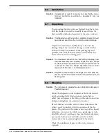
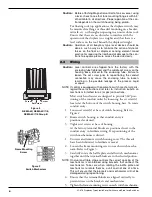
1. Loosen set screw(s) at base of switch housing. Refer to
Figure 2.
2. Rotate switch housing so that conduit entry is
positioned as desired.
3. Tighten set screws at base of housing.
At the factory, terminal blocks are positioned next to the
conduit entry to facilitate wiring. If repositioning of the
switch mechanisms is desired:
1. Unscrew and remove switch housing cover. The threads
have been lubricated to facilitate removal.
2. Loosen the frame mounting screw on each switch mecha-
nism. Refer to Figure 3.
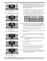
3. Carefully rotate the baffle plate and all switch mechanisms
together until the terminal blocks are in the desired position.
NOTE: On dual and triple stage controls the correct spacing of the
mechanisms is maintained using brackets that connect the
mechanisms. Take care when rotating the baffle plate and
mechanisms to rotate them as a unit and not one at a time.
This will ensure that the brackets and mechanisms will not be
damaged during repositioning.
4. Ensure that the terminal blocks are aligned vertically to
prevent stress on the brackets and mechanisms.
5. Tighten the frame mounting screw on each switch mechanism.
Set Screw
Screw
Screw
Figure 2
NEMA 4X, NEMA 4X/7/9,
NEMA 4X/7/9 Group B
Figure 3
Switch Mechanism
Frame Mounting
Screw


