32
45-610 Displacer Type Liquid Level Switches and Proof-er
®
Switches
4.3
Specifications
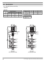
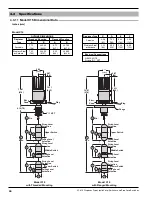
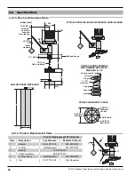
4.3.13 Proof-er Dimensional Data
Inches (mm)
TyPICAL PrOOF-Er INSTALLATION WITH vErSA FLANGE
vErSA FLANGE ASSEMBLy
PArT NUMBEr 089-5207-001
MAX ANGLE = 15
°
vErSA FLANGE BOLT CIrCLE
HOLLOW BrASS DISPLACEr
5.93
(151)
4.29 (109)
14.62 (371)
Minimum
clearance
required
for actuation
30' (9 m)
SS
Cable
standard
1" NPT
2
1⁄2
" NPT
20' (6 m)
Cable standard
Optional flange
C
E
B
A
G
D
F
4.38 (111)
Diameter
cut out
5.44 (138)
Bolt circle
6.56 (167)
Diameter
.36 (9) Hole
Self-tapping bolts (4)
Gasket
Flange
O-Ring
Flange
2½" NPT
connection
Lock washers(4)
➁
➂
➃
➀
➄
Proof-er replacement Part Number
Item
Description
Low Pressure
Medium Pressure
1
Handle
004-4011-001
004-0490-001
2
O-Ring
Not Required
012-2205-001
3
Spring
013-2502-001
4
Cable Assembly
089-5807-001
5
O-Ring Cover
Not Required
004-0489-001
6
Nut
010-2107-004
Not Required
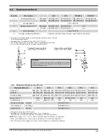
4.3.14 Proof-er replacement Parts
➅
B
D
F

