


1-11-10
E9E8ABLP
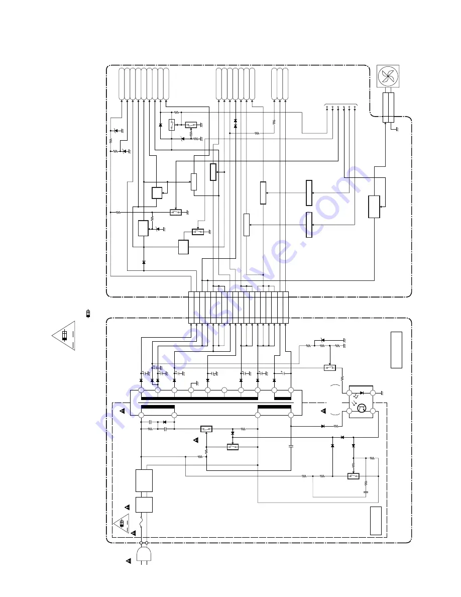
Power Supply Block Diagram
A V
AC1001
F1001
1A 250V
LINE
FILTER
L1001
D1001 - D1004
BRIDGE
RECTIFIER
2
4
Q1001
Q1003
Q1008
8
7
3
4
IC1010
ERROR
VOLTAGE DET
HOT
COLD
T1001
Q1055
Q1052
Q1102
Q1103
POWER SUPPLY CBA
MAIN CBA
F
HOT CIRCUIT. BE CAREFUL.
20
19
18
17
16
15
14
13
12
11
11
AL+44V
22
AL+12V(1)
33
AL+12V(2)
4
AL+12V(2)
5
D
VD+5V
8
A
L+5V
17
AL-30V
19
AL+3V
20
AL+3V
25
AL+4V
29
F1
30
F2
CN1607
CN1101
1
2
1
FAN
2
GND
CN1102
TO
SYSTEM CONTR
O
L
BLOCK DIA
GRAM
P-ON-L
F
A
N-CONT
EV+33V
AL+18V
EV+11V
P-ON+9V
P-ON+5V
AL+5V
AL-30V
F1
-FL
F2
EV+10.5V
PWR-SW
FAN
TIMER+5V
Q1056
Q1101
Q1031
AL+12V
P-ON+5V
6
D
VD+5V
7
D
VD+5V
18
AL+3V
26
AL+4V
27
AL+4V
28
AL+4V
P-DO
WN-H
P-ON+3.3V
EV+2.4V
P-ON+5V
P-ON+11V
+9V
REG.
SW+5V
SW+5V
SW
+11V
Q1104
Q1105
Q1057
SW
+5V
+3.3V REG
IC2503
+1.8V REG
IC2504
P-ON+1.8V
Q1107, Q1108
FAN
CONTROL
REG-CONT1
REG-CONT2
SWITCHING
Q2205
SWITCHING
Q2206
4
5
8
17
19
20
25
29
30
6
7
18
26
27
28
CAUTION !
Fixed voltage (or Auto voltage selectable) power supply circuit is used in this unit.
If Main Fuse (F1001) is blown , check to see that all components in the power supply
circuit are not defective before you connect the AC plug to the AC power supply.
Otherwise it may cause some components in the power supply circuit to fail.
NOTE:
The voltage for parts in hot circuit is measured using
hot GND as a common terminal.
"Ce symbole reprèsente un fusible à fusion rapide."
CAUTION !
For continued protection against fire hazard,
replace only with the same type fuse.
ATTENTION : Pour une protection continue les risqes
d'Incele n'utiliser que des fusible de m
ê
me type.
Risk of fire
-replace fuse as marked.
"This symbol means fast operating fuse."
A V
F
Содержание ZV420MW8 - DVDr/ VCR Combo
Страница 19: ...1 6 6 E9E8ADC Fig D10 19 Deck Pedestal 20 Front Bracket R S 18 S 18 S 18 S 18 S 19 ...
Страница 39: ...1 12 3 Main 1 7 Schematic Diagram E9E8ASCM1 ...
Страница 41: ...1 12 5 Main 3 7 Schematic Diagram E9E8ASCM3 ...
Страница 42: ...1 12 6 Main 4 7 Schematic Diagram E9E8ASCM4 ...
Страница 43: ...1 12 7 Main 5 7 Schematic Diagram E9E8ASCM5 ...
Страница 44: ...1 12 8 Main 6 7 Schematic Diagram E9E8ASCM6 ...
Страница 45: ...1 12 9 Main 7 7 Schematic Diagram E9E8ASCM7 ...
Страница 47: ...1 12 11 Front Jack Schematic Diagram E9E8ASCFJ ...
Страница 63: ...1 15 3 R4NTI Push close 0 08 V 0 02 s Push Close detection Threshold level ...
Страница 69: ...1 18 2 E9E8APEX Packing S1 A14 S2 Unit S3 Some Ref Numbers are not in sequence X1 X22 X4 X20 X5 X2 S2 ...


