


1-7-1
E9C80EA
ELECTRICAL ADJUSTMENT INSTRUCTIONS
General Note: “CBA” is abbreviation for
“Circuit Board Assembly.”
NOTE:
1. Electrical adjustments are required after replacing
circuit components and certain mechanical parts.
It is important to do these adjustments only after
all repairs and replacements have been
completed. Also, do not attempt these adjustments
unless the proper equipment is available.
2. To perform these alignment / confirmation
procedures, make sure that the tracking control is
set in the center position: Press either [CHANNEL
L
] or [CHANNEL
K
] button on the front panel first,
then the [PLAY] button on the front panel.
Test Equipment Required
1. Oscilloscope: Dual-trace with 10:1 probe,
V-Range: 0.001~50 V/Div.,
F-Range: DC~AC-20 MHz
2. Alignment Tape (FL8A)
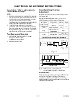
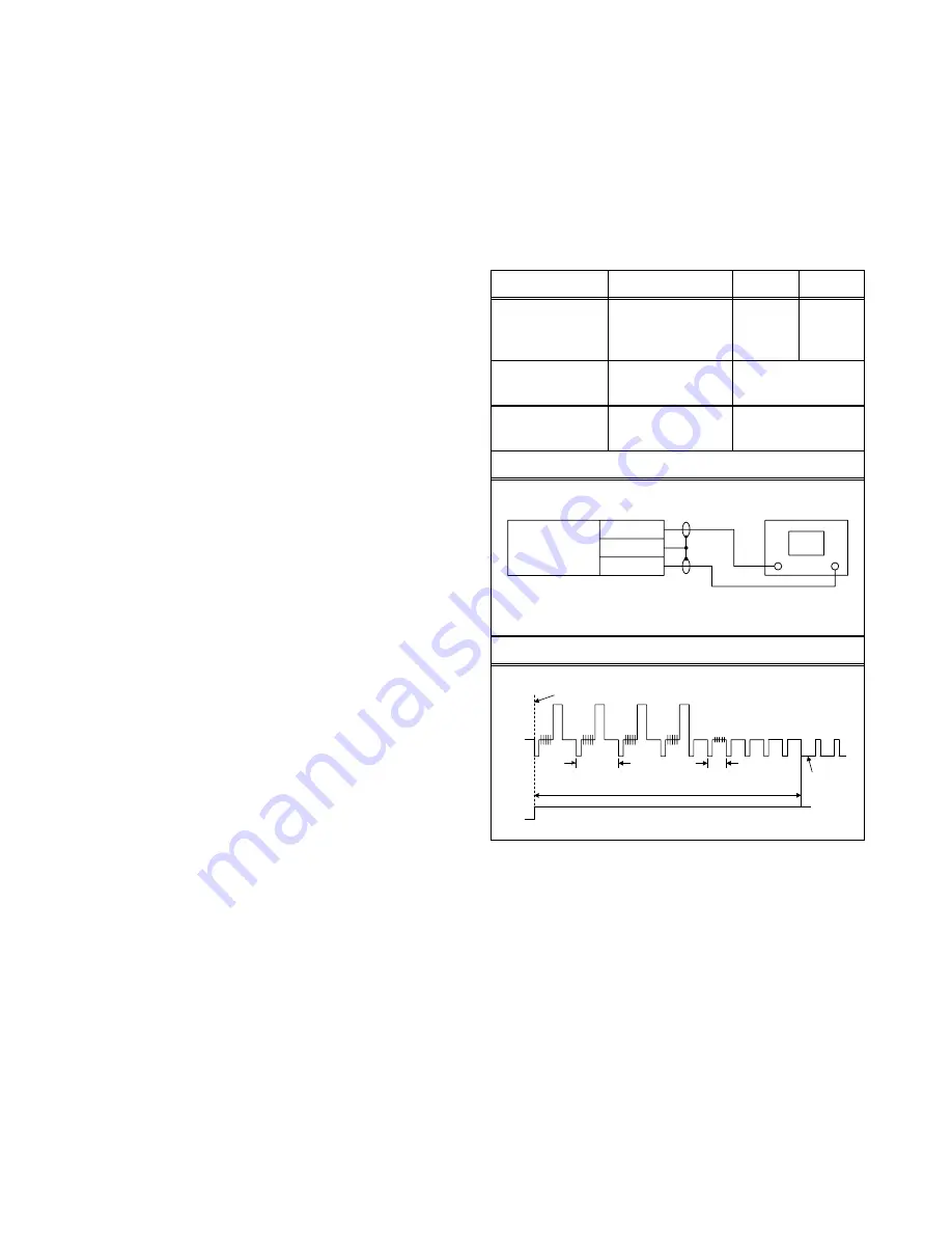
Head Switching Position
Adjustment
Purpose: To determine the Head Switching position
during playback.
Symptom of Misadjustment: May cause Head
Switching noise or vertical jitter in the picture.
Note: TP751(V-OUT),
TP302(RF-SW),
VR1501(Switching Point) --- Main CBA
Reference Notes:
Playback the Alignment tape and adjust VR501 so that
the V-sync front edge of the CH1 video output
waveform is at the 6.5H ± 1H (412.7
µ
s ± 63.5
µ
s)
delayed position from the rising edge of the CH2 head
switching pulse waveform.
Test point
Adj. Point
Mode
Input
TP751(V-OUT)
TP302(RF-SW)
GND
VR1501
(Switching Point)
PLAY
(SP)
-----
Tape
Measurement
Equipment
Spec.
FL8A
Oscilloscope
6.5H ± 1H
(412.7
µ
s±63.5
µ
s)
Connections of Measurement Equipment
Figure 1
Oscilloscope
Main CBA
TP751
CH1 CH2
Trig. (+)
GND
TP302
EXT. Syncronize Trigger Point
1.0H
CH1
CH2
Switching Pulse
V-Sync
0.5H
6.5H
±
1H (412.7
µ
s
±
63.5
µ
s)
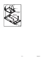
Содержание ZV420MW8 - DVDr/ VCR Combo
Страница 19: ...1 6 6 E9E8ADC Fig D10 19 Deck Pedestal 20 Front Bracket R S 18 S 18 S 18 S 18 S 19 ...
Страница 39: ...1 12 3 Main 1 7 Schematic Diagram E9E8ASCM1 ...
Страница 41: ...1 12 5 Main 3 7 Schematic Diagram E9E8ASCM3 ...
Страница 42: ...1 12 6 Main 4 7 Schematic Diagram E9E8ASCM4 ...
Страница 43: ...1 12 7 Main 5 7 Schematic Diagram E9E8ASCM5 ...
Страница 44: ...1 12 8 Main 6 7 Schematic Diagram E9E8ASCM6 ...
Страница 45: ...1 12 9 Main 7 7 Schematic Diagram E9E8ASCM7 ...
Страница 47: ...1 12 11 Front Jack Schematic Diagram E9E8ASCFJ ...
Страница 63: ...1 15 3 R4NTI Push close 0 08 V 0 02 s Push Close detection Threshold level ...
Страница 69: ...1 18 2 E9E8APEX Packing S1 A14 S2 Unit S3 Some Ref Numbers are not in sequence X1 X22 X4 X20 X5 X2 S2 ...


