
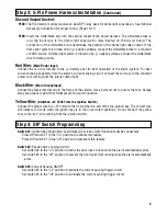


Step 3: 5-Pin Power Harness Installation
The power harness contains 3 wires and two vacant sockets. Packaged with the 10-pin main harness are
two loose wires an orange wire and a white wire with black stripe. The orange and white/black wires are
only used with PL60 model only. Follow the wiring recommendations enclosed for each wire.
4
Step 2: 10-Pin Main Harness Installation
(Continued)
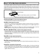
Violet Wire:
(Positive Door Pin Switch Input)
The violet wire connects to the common wire of the vehicle that switches on the dome light. Normally
this wire is located at one of the door jamb switches. For some vehicles it may be necessary to connect
the violet wire directly to the switched turn on wire at the dome light. The violet wire connects to positive
switched circuits only.
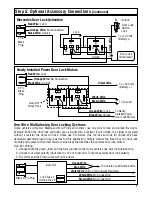
Second Vacant Socket:
The second vacant wire socket provides a 1 second pulsed ground (300mA) output when channel #2 is
activated. (See Optional Accessory Connections) (Page 11)
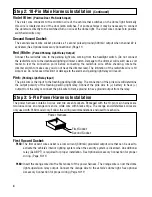
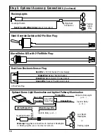
Red / White:
(Pulsed Parking Light Relay Output)
Connect the red/white wire to the parking light wire coming from the headlight switch. (Do not connect
the red/white wire to the dashboard lighting dimmer switch. Damage to the dimmer will result) use a volt
meter to test the connection point before connecting the red/white wire. While checking, rotate the
dimmer switch to make sure you do not have the dimmer lead. The limitation of the red/white wire is 10
Amp max. Do not exceed this limit or damage to the alarm and parking light relay will result.
Pink:
(Parking Light Relay Input)
The pink wire is the input to the flashing parking light relay. The connection of the pink wire will determine
the output polarity of the flashing parking light relay. Connect the pink wire to (+) battery to have (+)
output from the relay or connect the pink wire to frame ground to have ground output from the relay.
Power Harness
First Socket
Second Socket
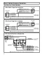
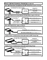
First Vacant Socket:
PL50: The first vacant wire socket is a low current (300mA) grounded output wire that can be used to
activate the vehicle’s interior lighting system when the security system is disarmed. An additional
relay (ALA-RPT) is required for proper installation. See Optional Accessory Connection for proper
wiring. (Page 10-11)
PL60: Insert the orange wire into the first socket of the power harness. The orange wire is now the dome
light supervision relay output. Connect the orange wire to the vehicle’s dome light. See optional
Accessory Connection for proper wiring (Page 10-11)