


Step 2: 10-Pin Main Harness Installation
The main wire harness contains 8 wires which all have a specific purpose. Follow the wiring
recommendations enclosed for each wire. Wires not used should be released from the harness connector
or taped off to prevent accidental shorting. Included with the 10-pin wire harness are two loose wires, an
orange wire and a white wire with black stripe. See main harness and power harness wiring instructions
for these two loose wires.
3
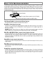
Vacant Sockets
Main Harness
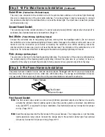
First Vacant Socket (Located in the 1st Position)
Second Vacant Socket (Located in the 8th Position)
First Vacant Socket:
(For Use with ALA-RPT Relay Pack Only)
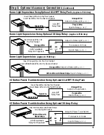
See Optional Accessory Connection for proper wiring. (Page 11)
Gray Wire:
(Pulsed Ground for Car Horn)
The gray wire is a pulsed ground output designed to activate the vehicle’s existing car horn system in
place of or in addition to a siren sounding device. Connect the gray wire to the negative trigger wire on
the vehicle’s horn relay.
WARNING! Maximum output of this wire is 300mA. Horn systems requiring positive voltage or more than
300mA to trigger the horn relay will require an additional relay to increase current capabilities.
Blue Wire with White Stripe:
(Channel #3 Output) (Applies to PL60 Only)
Connect the blue/white wire to the device that will be operated from channel #3 of the alarm system. The
blue/white wire has a current capacity of 300mA “maximum”. This output is activated by pressing down
button #3 and holding it. The blue/white wire will provide a grounded signal as long as button #3 on the
transmitter is held down.
Brown Wire:
(Positive Output for Optional Siren)
Connect the brown wire to the positive wire from the siren. Ground the remaining wire from the siren for
proper operation.
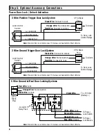
Blue Wire:
(Optional Grounding Sensor Input)
The blue wire is an instant grounding trigger input for optional hood/trunk grounded pin switches or any
electronic sensor.
Green Wire:
(Grounded Door Pin Switch Input)
The green wire connects to the common wire of the vehicle that switches on the dome light. Normally
this wire is located at one of the door jamb switches. For some vehicles it may be necessary to connect
the green wire directly to the switched turn on wire at the dome light. The green wire connects to
negative switched circuits only.