Magikist HWG20 Скачать руководство пользователя страница 7

-3-

4.1 LOCATION

1) The water heater contains sensitive electronic

components that must not be exposed to water
spray. Choose a location such that the heater
will not be exposed to water spray of any kind.
Failure to do so may result in damage to
electronic components and void the warranty
on such components.

2) The water heater is approved for installation on

non-combustible material with 6 inches of
clearance from combustible walls. A minimum
clearance of 48 inches is required on the heater
front for access.

3) The water heater must be located in an area

that is protected from the weather and locations
where flooding may occur. 

Avoid drafty

locations that may cause pilot outage

.

4) In repair garages, the point of ignition shall be

not less than 4.5 feet (54 inches) above the
floor.

5) The location of the heater should be in an area

away from moving vehicles and should be
provided with sufficient protection and support
to prevent damage.

6) If the heater is being installed with a high

pressure pump, the heater should be installed
in a suitable dry location as near to the high
pressure pump unit as practical to simplify
connecting the water supply lines and electrical
lines between the two units.

4.2 MOUNTING

The heater must be mounted to a solid, non-
combustible base. Mounting holes are provided on
the inside bottom of the heater. The HWG40 has
four 1/2” holes while the HWG20 has three 1/2”
holes.

4.3 GAS SUPPLY

1) Pipe sizing must conform to local and

applicable codes (CGA B149.1 and B149.2).

2) Natural gas and LP (propane) heaters

incorporate different components such that they
are not interchangeable. Never supply LP
(propane) to a natural gas heater or natural gas
to a LP (propane) heater.

CAUTION: Unlike natural gas, LP (propane)
gas is heavier than air. If pilot outage should
occur, the floor areas should be vented and
blown clear before relighting the pilot.
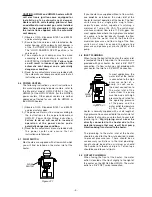
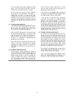
IMPORTANT:
Licensed gas installer MUST ensure:

– 3.5" W.C. for natural gas heaters or
– 11" W.C. using an external regulator for LP

gas heaters

measured at the Pressure Tap Port on the gas
valve as shown in figure 4.3.1.

4.4 VENTING

1) Observe C.G.A. Standards B149.1 and B149.2

and local safety codes.

2) The draft hood furnished with the heater must

be attached to the flue outlet without alteration
using the same size vent as the draft hood
outlet (see specifications for flue diameter).

3) For venting in general, do not reduce size of

vent. Reductions in vent sizing for power
venters must be made after the draft hood. For
horizontal runs, maintain 1/4 inch pitch per foot.
Top of stack to be 2 feet above highest part of
roof or nearby obstructions.  Provide an
approved cap for the stack outlet. Refer to
C.G.A. standards.

4) Use of type “B” venting is recommended and

must be installed in accordance with C.G.A.
standards B149.1 and B149.2 by qualified
personnel.

5) Provisions for other water heaters and/or other

gas fired appliances within the same enclosure
as the heater must be made to allow for ample
free air to enter the enclosure for combustion
and venting

.

Failure to supply adequate free

air may result in the dangerous
accumulation of combustion gas and/or
severe damage to the heater coil, due to
reverse drafting of air down the heater vent.
If necessary, an automatic vent damper or
power venter should be installed.

4.5 AUTOMATIC VENT DAMPER

The following instructions, and all instructions in
this manual pertaining to automatic vent dampers,
refer to the Magikist model HWG-AD10 (for the
HWG40) or the HWG-AD7 (for the HWG20)
automatic vent dampers. Other vent dampers are
neither approved not tested for use with the
HWG40 or the HWG20 heaters.

Pressure Tap

Port

0

1

2

3

4

5

6

1
2
3
4
5
6

4.0  INSTALLATION

*** HEATERS MUST BE INSTALLED BY QUALIFIED PERSONNEL ONLY ***

Figure 4.3.1


Содержание HWG20

Страница 1: ...DEL HWG40 MODEL HWG20 GAS FIRED COMMERCIAL INDUSTRIAL PRESSURE WASHER HEATERS INSTRUCTION MANUAL V3 02 For heaters equipped with ProSafe II control and 24V electronic ignition HSI or 24V standing pilo...

Страница 2: ...this page was intentionally left blank...

Страница 3: ...INDICATOR 10 6 4 REQUEST FOR HEAT INDICATOR 10 6 5 PURGE DELAY ON INDICATOR 10 6 6 FLOW ON INDICATOR 10 6 7 THERMOSTAT INDICATOR 10 6 8 EXTERIOR CONTROL INDICATOR 10 6 9 FLUE STATUS INDICATOR 11 6 10...

Страница 4: ...this page was intentionally left blank...

Страница 5: ...rovide safe and effective control of the heater The PROSAFE II control provides visual status to the operator of the heater through a front panel display on the heater Should some condition arise whic...

Страница 6: ...injury Always keep clear of the spray nozzle Do not direct discharge stream at people or electrical apparatus 3 Always keep clear of moving belts and pulleys 4 Never disconnect high pressure hose dur...

Страница 7: ...t outage should occur the floor areas should be vented and blown clear before relighting the pilot IMPORTANT Licensed gas installer MUST ensure 3 5 W C for natural gas heaters or 11 W C using an exter...

Страница 8: ...w normally open switch capable of switching a minimum of 1 amp at 24 VAC The switch must also have minimum flow rate of 1 0 U S gpm For most applications where the high pressure output of a pump is to...

Страница 9: ...uctions later on in this section The second wiring configuration is used when installing the heater without a Magikist control panel If 24VAC is not available you will need to mount the supplied trans...

Страница 10: ...tallations that do not utilize a Magikist control panel and another component of your system requires the flow switch for some control aspect the black wire and the EXT FLOW blue wire may be used to d...

Страница 11: ...ions on adjusting the flow switch If the DAMPER OPEN indicator does not follow the steps below refer to section 11 0 TROUBLESHOOTING 1 Turn on the high pressure pump or other source supplying water to...

Страница 12: ...nob from pilot to on initially due to air inside the gas valve If this occurs repeat the steps in section 5 5 4 If the water inlet of the heater is connected to a high pressure pump start the pump and...

Страница 13: ...h affect the operation of the heater are detected and displayed to the operator by the PROSAFE II control Following is a description of the indicators and their function on the PROSAFE II control 6 1...

Страница 14: ...flashing slow the PROSAFE II control is indicating a warning that there is water flow through the heater and that it has been continuous for at least 10 minutes This warning is strictly for informatio...

Страница 15: ...ose the damper only after there is no water flow for a preset period of time This eliminates the on off cycling a damper experiences in high pressure wash systems where wash guns are opened and closed...

Страница 16: ...nt the heater from firing Warning conditions should be attended to promptly in order to ensure the continued safe operation of the heater Should a warning condition arise the indicator light that rela...

Страница 17: ...ing another pilot trial period The SmartValve is a continuous retry control Thus it will continuously repeat the pilot trial period followed by the 5 minute delay period until the pilot is successfull...

Страница 18: ...burner 9 3 CARE OF MAIN BURNERS Due to condensation from heater coils dripping on the burners a scale build up may occur in the burner jet orifices To remove the burner bar from the heater turn off th...

Страница 19: ...an approved coil cleaner may be required See section 8 4 CLEANING HEATER COIL OF SCALE for more information 10 3 FREEZING CONDITIONS Freezing conditions can result in severe damage to the heater coil...

Страница 20: ...out frequently standing pilot heaters only Heater is in location that is too drafty Pilot assembly requires service Relocate heater See section 4 1 LOCATION Have gas service personnel check operation...

Страница 21: ...ue are at or near freezing Take necessary steps to increase temperature in flue so that coil does not freeze DAMPER OPEN indicator is always on If an automatic vent damper is not installed then this i...

Страница 22: ...rature sensor if necessary Temperature setting display flashes E21 and THERMOSTAT indicator is flashing Communicaton problem with temperature sensor short Check connection of temperature sensor to PRO...

Страница 23: ...20...

Страница 24: ...21...

Страница 25: ...SENS TEMP SENS FLOW SW OUTPUT DAMPER brown black 24vac supply black black purple purple blue grey yellow white Refer to manual for wiring of purple blue grey yellow white Duplicate black wires for co...

Страница 26: ...SENS FLOW SW OUTPUT DAMPER brown black black black purple purple blue grey yellow Refer to manual for wiring of purple blue grey yellow white Duplicate black wires for convenience Electrical Connecti...

Страница 27: ...2 Depth 32 Height without draft hood 46 Height with draft hood 66 3 4 Shipping weight 418 lbs HWG20 Type Instantaneous steel coil Gas supply Natural N models LP P models Coil specifications 3 4 I P S...

Страница 28: ...ation any warranties or merchantability or fitness for a particular purpose and all such warranties are hereby disclaimed and excluded by the manufacturer Repair or replacement of defective products a...

Отзывы: