Magikist HWG20 Скачать руководство пользователя страница 18

-14-

9.1 FLOW SWITCH (MODEL HPFS38)

On heaters where the mineral content of the water
is high or where chemicals or soaps are used, it
may be necessary on occasion to

disassemble the housing

and clean any debris and
build up inside the flow
switch. This maintenance
will allow the magnet to
continue to move smoothly
and freely, and will
eliminate nuisance failures
due to scale buildup. It is
suggested that the flow
switch be inspected and
cleaned as necessary
each time the heater (or
possibly the high pressure
pump) receives routine
maintenance or service.

To adjust the flow switch, the reed switch will need
to be repositioned. The reed switch is housed
inside the cylindrical metal can from which the
jacketed wire comes out. To reposition the reed
switch loosen the friction bolt/nut and slide the
cylindrical metal can in or out such that the FLOW
indicator is on when there is flow and off when
there is no flow through the switch. Retighten the
friction bolt/nut to secure the position of the reed
switch.

9.2 RELIGHTING THE PILOT BURNER

(STANDING PILOT HEATERS ONLY)
CAUTION: Should pilot outage occur, wait 5
minutes before relighting to clear combustion
chamber of accumulated gas. If an automatic
vent damper is installed,  you must also move
the service switch on the motor housing of the
vent damper to “HOLD DAMPER OPEN”
position and wait 5 minutes before relighting
(return switch to “AUTOMATIC OPERATION”
once relighting procedure is complete).
Because LP (propane) gas is heavier than air,
heaters utilizing these gases should have the
floor areas vented and blown clear before
relighting the pilot.

WARNING:

IF YOU SMELL GAS, SHUT OFF THE GAS
SUPPLY TO THE APPLIANCE AND
EXTINGUISH ANY OPEN FLAME. IF THE
ODOUR PERSISTS, CALL YOUR GAS
INSTALLER IMMEDIATELY.

ADVERTISSEMENT

:

SI UNE ODEUR DE GAZ EST DÉCELÉE,
COUPER L’ALIMENTATION EN GAZ DE
L’APPAREIL ET ÉTEINDRE TOUTES LES
FLAMMES. SI L’ODEUR PERSISTE, AVERTIR
IMMÉDIATEMENT LE FOURNISSEUR DE GAZ.

Should pilot outage occur, refer to section 5.5
LIGHTING THE PILOT BURNER for instructions
on relighting the pilot burner.

9.3 CARE OF MAIN BURNERS

Due to condensation from heater coils dripping on
the burners, a scale build-up may occur in the
burner jet orifices.

To remove the burner bar from the heater, turn off
the gas to the heater  by turning the knob on the
gas valve to the “off” position. For standing pilot
heaters, disconnect the pilot tube and
thermocouple at the gas valve. For electronic
ignition heaters, disconnect the pilot tube and the
electrical connections between the pilot assembly
and the electronic ignition module (take care to
note the connections so that they may be
reconnected correctly). Disconnect the union
joining the burner bar to the modulating gas valve,
and the U-bolt retaining the feed pipe at the
bottom of the heater inside the door. Slide the
burner bar out through the shell opening.

To clean burner jets select the proper size drill for
type of gas involved. Use a pin vise to hold the
drill and ream out each jet orifice by hand. It is
recommended that the burner jets not be removed
from the burner bar except for jets that require
replacing. 

Do not ream out orifices to a larger

size than shown.

HWG40:
#55 drill for natural gas 0-2000ft. (0-610 m)
#56 drill for natural gas 2000-4000ft. (610-1370 m)
#68 drill for LP gas 0-2000ft. (0-610 m)
#70 drill for LP gas 2000-4000ft. (610-1370 m)
HWG20
#52 drill for natural gas 0-2000ft. (0-610 m)
#53 drill for natural gas 2000-4000ft. (610-1370 m)
#63 drill for LP gas 0-2000ft. (0-610 m)
#64 drill for LP gas 2000-4000ft. (610-1370 m)

9.4 CLEANING HEATER COIL OF SCALE

Excessive scale in heater coils can reduce the
recovery rate of the heater and restrict the flow of
water through the heater. Use of hard water
through the heater tends to accelerate scale build-
up. Should heater coils develop excessive scale
build-up it may be necessary to use a coil cleaner
to remove the scale build-up. Use only an
approved coil cleaner specially designed for
cleaning scale and mineral deposits from steel
coils, such as Magikist 

M

AGIK

C

OIL

de-liming acid.

To clean the heater coil of scale build-up, follow
the directions provided with the coil cleaner. Never
allow the coil cleaner to sit in the coil overnight or
for long periods of time. Always flush out the coil
thoroughly with water after cleaning.
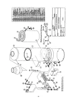
9.0  MAINTENANCE

Figure 9.1.1


Содержание HWG20

Страница 1: ...DEL HWG40 MODEL HWG20 GAS FIRED COMMERCIAL INDUSTRIAL PRESSURE WASHER HEATERS INSTRUCTION MANUAL V3 02 For heaters equipped with ProSafe II control and 24V electronic ignition HSI or 24V standing pilo...

Страница 2: ...this page was intentionally left blank...

Страница 3: ...INDICATOR 10 6 4 REQUEST FOR HEAT INDICATOR 10 6 5 PURGE DELAY ON INDICATOR 10 6 6 FLOW ON INDICATOR 10 6 7 THERMOSTAT INDICATOR 10 6 8 EXTERIOR CONTROL INDICATOR 10 6 9 FLUE STATUS INDICATOR 11 6 10...

Страница 4: ...this page was intentionally left blank...

Страница 5: ...rovide safe and effective control of the heater The PROSAFE II control provides visual status to the operator of the heater through a front panel display on the heater Should some condition arise whic...

Страница 6: ...injury Always keep clear of the spray nozzle Do not direct discharge stream at people or electrical apparatus 3 Always keep clear of moving belts and pulleys 4 Never disconnect high pressure hose dur...

Страница 7: ...t outage should occur the floor areas should be vented and blown clear before relighting the pilot IMPORTANT Licensed gas installer MUST ensure 3 5 W C for natural gas heaters or 11 W C using an exter...

Страница 8: ...w normally open switch capable of switching a minimum of 1 amp at 24 VAC The switch must also have minimum flow rate of 1 0 U S gpm For most applications where the high pressure output of a pump is to...

Страница 9: ...uctions later on in this section The second wiring configuration is used when installing the heater without a Magikist control panel If 24VAC is not available you will need to mount the supplied trans...

Страница 10: ...tallations that do not utilize a Magikist control panel and another component of your system requires the flow switch for some control aspect the black wire and the EXT FLOW blue wire may be used to d...

Страница 11: ...ions on adjusting the flow switch If the DAMPER OPEN indicator does not follow the steps below refer to section 11 0 TROUBLESHOOTING 1 Turn on the high pressure pump or other source supplying water to...

Страница 12: ...nob from pilot to on initially due to air inside the gas valve If this occurs repeat the steps in section 5 5 4 If the water inlet of the heater is connected to a high pressure pump start the pump and...

Страница 13: ...h affect the operation of the heater are detected and displayed to the operator by the PROSAFE II control Following is a description of the indicators and their function on the PROSAFE II control 6 1...

Страница 14: ...flashing slow the PROSAFE II control is indicating a warning that there is water flow through the heater and that it has been continuous for at least 10 minutes This warning is strictly for informatio...

Страница 15: ...ose the damper only after there is no water flow for a preset period of time This eliminates the on off cycling a damper experiences in high pressure wash systems where wash guns are opened and closed...

Страница 16: ...nt the heater from firing Warning conditions should be attended to promptly in order to ensure the continued safe operation of the heater Should a warning condition arise the indicator light that rela...

Страница 17: ...ing another pilot trial period The SmartValve is a continuous retry control Thus it will continuously repeat the pilot trial period followed by the 5 minute delay period until the pilot is successfull...

Страница 18: ...burner 9 3 CARE OF MAIN BURNERS Due to condensation from heater coils dripping on the burners a scale build up may occur in the burner jet orifices To remove the burner bar from the heater turn off th...

Страница 19: ...an approved coil cleaner may be required See section 8 4 CLEANING HEATER COIL OF SCALE for more information 10 3 FREEZING CONDITIONS Freezing conditions can result in severe damage to the heater coil...

Страница 20: ...out frequently standing pilot heaters only Heater is in location that is too drafty Pilot assembly requires service Relocate heater See section 4 1 LOCATION Have gas service personnel check operation...

Страница 21: ...ue are at or near freezing Take necessary steps to increase temperature in flue so that coil does not freeze DAMPER OPEN indicator is always on If an automatic vent damper is not installed then this i...

Страница 22: ...rature sensor if necessary Temperature setting display flashes E21 and THERMOSTAT indicator is flashing Communicaton problem with temperature sensor short Check connection of temperature sensor to PRO...

Страница 23: ...20...

Страница 24: ...21...

Страница 25: ...SENS TEMP SENS FLOW SW OUTPUT DAMPER brown black 24vac supply black black purple purple blue grey yellow white Refer to manual for wiring of purple blue grey yellow white Duplicate black wires for co...

Страница 26: ...SENS FLOW SW OUTPUT DAMPER brown black black black purple purple blue grey yellow Refer to manual for wiring of purple blue grey yellow white Duplicate black wires for convenience Electrical Connecti...

Страница 27: ...2 Depth 32 Height without draft hood 46 Height with draft hood 66 3 4 Shipping weight 418 lbs HWG20 Type Instantaneous steel coil Gas supply Natural N models LP P models Coil specifications 3 4 I P S...

Страница 28: ...ation any warranties or merchantability or fitness for a particular purpose and all such warranties are hereby disclaimed and excluded by the manufacturer Repair or replacement of defective products a...

Отзывы: