9
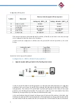
Configuration of the system
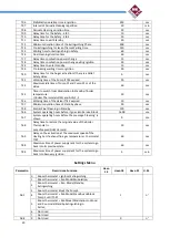
Symbols
Components
Presence inside the apparel of the components
Heating only (HEVO__-R)
H Hot water (HEVO__-P)
P1
Boiler circulator
PRESENT
PRESENT
P2
Secondary circulator or
electrovalve
NOT PRESENT
PRESENT
FL
Flussostate
NOT PRESENT
NOT PRESENT
S1
Boiler Probe
PRESENT
PRESENT
S2
Puffer Probe
NOT PRESENT
NOT PRESENT
All not present components could be added during the installation, followed by a correct electric connection and a right
electric configuration that will be shown in the next chapters
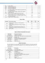
In order to set the best configuration it is sufficient to vary the parameter P26 inside the System Menu, in the section
Settings.
Variation Parameter
Type of Plant
P26 = 0
Configuration 0
P26 = 2
Configuration 2
P26 = 4
Configuration 4
Hereafter the function logics will be explained
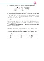
Configuration 0 – P26=0 – Default from production
Apparel coupled with a gas boiler in the ‘heating only’ version
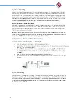
In order to connect the boiler to another (gas) boiler on a Hydraulic plant with closed vessel, it is suggested,
according to the current norms, to install a Plate exchanger that separates the hydraulic circuits of the 2
heat generators. The function of the pellet boiler is priority with respect to the activity of the second
generator, since the cheapest fuel is pellet. The central unit is able to control automatically the activity
between the two apparels by the connection of a motorized valve 3 ways.
In this case the Boiler Probe (S1) detects the temperature of the body of the machine in the boiler; once
that the probe reaches 50° (Th 19), the circulator P1 of the boiler begins to exchange with the plant and the
motorized valve P2 with thermostat set at 50° (Th 56) opens the circuit between the plant and the boiler.
Содержание HEVO 14
Страница 1: ...TECHNICAL MANUAL HEVO 14 18 21 ENGLISH...


