508196-01
Issue 2120
Page 5 of 18
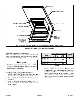
Wall Sleeve and Louver Installation
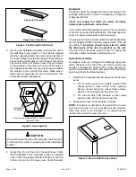
Refer to installation instructions included with the wall
sleeve kit and the louver kit along with Figure 3 for guidance
in assembling and installing the wall sleeve and louver.
The sleeve is not intended as the sole support for
the unit. An additional support must be provided for
adequate support (see Figure 3).
CAUTION
Installing and Securing Unit to Wall Sleeve
1. Before installing and securing the unit to the wall
sleeve, make sure that the proper louver is installed.
2. Make sure the gaskets attached to the sleeve are not
damaged.
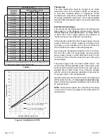
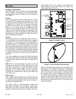
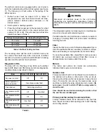
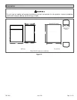
3. Verify divider panel is positioned properly. Refer to
Table 2 for wall sleeves that allow for multiple divider
panel locations.
Model
ASLEEVE**-2 ASLEEVE**-5
Orientation
of Flange
Two
Positions
Three
Positions
MHP4-12-09,12
Lower
Lower
Down
MHP4-12-18
Up
MHP4-12-24, 30
Upper
Middle
MHP4-14-36
N/A
Upper
Table 2.
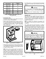
4. Place the unit into the wall sleeve.
Lift leading end
of unit and walk unit onto the sleeve.
Once in the
wall sleeve, lower the unit into position. This prevents
damage to the base pads. Assure that the unit is level
and completely seated against the gaskets on the wall
sleeve. The unit must be supported by a field supplied
base platform.
Figure 3. Wall Sleeve and Louver Kit Installation
NOTE:
Unit must be supported by platform, which must be level with sill plate of opening in exterior wall.
Exterior Wall
Wall Sleeve Top Panel
Wall Sleeve Side Panel
Platform
(field fabricated
and supplied)
Platform Height: Minimum 4”
3/4” Board Added to
Level Platform with
Wall Sleeve Base
(provided with
wall Sleeve)
Lag Screws with Washers
Wall Sleeve Base
Wall Sleeve Side Panel
Wall Sleeve Divider Panel


