background image

507858-01

Issue 1922

Page 3 of 21

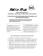
Figure 1. Minimum Clearances

Exterior Wall

Wall Sleeve

(one each side)

Interior Wall

Clearances*

Mounting Strap

(one each side)

3/4" Plywood Riser

Floor

4" Min.

Front of Unit

Sill Plate

Side View

Platform (field supplied) must be level with sill plate of hole in exterior wall. Unit must be 

supported by platform.

Top View

1"

Min.

1"

Min.

Front of Unit

Clearance to

Front of Unit*

Supply Duct

Opening

Return Duct

Opening

IMPORTANT

The unit must be installed with approved wall sleeve 

and grille accessories for safe operation. Improper 

installations could result in property damage, personal 

injury, or death.

Minimum Unit Clearance

Front*

Sides

1”

1”

* Added clearance must be provided for the 

gas supply line and drain trap installation.

Clearance to combustible materials is 0” at the side, 

top, and front of plenum. If accessibility clearances 

are greater than clearances to combustibles, 

accessibility clearances take precedence.

The front of the unit must be accessible for service. 

If the unit is enclosed, providing a door or access 

panel opposite the front of the unit is the preferred 

method of providing access. The door or access 

panel must be at least 30” wide (centered on the 

unit) and as tall as the unit.

Содержание MGE4 Series

Страница 1: ...aving jurisdiction should be consulted before installation is made Such applicable regulations or requirements take precedence over the general instructions in this manual CAUTION P507858 01 P 507858...

Страница 2: ...NING Installation and servicing of air conditioning equipment can be hazardous due to internal refrigerant pressure and live electrical components Only trained and qualified service personnel should i...

Страница 3: ...lle accessories for safe operation Improper installations could result in property damage personal injury or death Minimum Unit Clearance Front Sides 1 1 Added clearance must be provided for the gas s...

Страница 4: ...protection clearances There is no minimum clearance required on locating the unit to an interior corner of a building If the unit is installed in a residential garage it must be located or protected...

Страница 5: ...the mounting bracket Keep this screw Carbon Monoxide Poisoning Hazard Failure to follow the steps outlined below for each appliance connected to the venting system being placed into operation could re...

Страница 6: ...make sure that the proper louver kit is installed Due to the high temperatures of the combustion products released from the gas vent MGE gas package units require the use of either an aluminum louver...

Страница 7: ...c 0 4 w c 0 5 w c Rise Range F Mid Rise F SCFM Watts Temp Rise SCFM Watts Temp Rise SCFM Watts Temp Rise SCFM Watts Temp Rise SCFM Watts Temp Rise 3 4 Ton 15MGE4 11 091 P 15 45 30 TAP 1 FAN 430 46 370...

Страница 8: ...N A TAP 3 COOL N A N A N A N A 475 93 430 97 385 101 TAP 4 HEAT 450 50 40 405 53 44 355 57 50 N A N A N A N A N A N A TAP 5 HEAT N A N A N A N A N A N A 525 101 34 485 105 37 450 110 40 36MGE4 11 121...

Страница 9: ...N A N A TAP 3 COOL N A N A 765 184 730 191 675 201 630 206 TAP 4 HEAT 590 86 45 555 90 48 515 95 52 475 99 56 N A N A N A TAP 5 HEAT 715 129 38 680 135 39 650 140 41 615 146 44 585 151 46 48MGE4 11 18...

Страница 10: ...224 TAP 3 COOL 910 273 880 278 850 283 820 287 785 286 TAP 4 HEAT 600 89 45 560 93 48 520 96 52 485 100 56 N A N A N A TAP 5 HEAT N A N A N A 700 148 38 665 153 40 635 157 42 600 162 45 48MGE4 11 241...

Страница 11: ...38 670 141 40 635 146 42 600 151 45 48MGE4 11 301 P 35 65 50 TAP 1 FAN 490 55 465 65 435 72 415 81 390 89 TAP 2 COOL 930 239 900 243 885 250 835 256 805 262 TAP 3 COOL 1030 309 995 316 965 321 930 325...

Страница 12: ...38 685 135 39 650 140 41 615 145 44 48MGE4 11 361 P 35 65 50 TAP 1 FAN 615 82 580 86 540 91 500 96 450 102 TAP 2 COOL 1020 307 980 313 940 314 900 318 865 323 TAP 3 COOL 1040 329 1000 329 965 333 930...

Страница 13: ...Use thread sealant on the threaded fittings Install threaded fittings by hand only Do not over torque the fittings CAUTION Figure 6 Condensate Drain Installation Electrical Connections All wiring must...

Страница 14: ...r Fan Access Panel to Gas Valve and Burners Access Panel to Controls Manual Shutoff Valve with 1 8 NPT Plugged Tapping Accessible for Test Gauge Connection Field Supplied Filter Access Any conversion...

Страница 15: ...ed through flame sensor 5 Circulating air blower starts 30 seconds after the burners light 6 When the thermostat is satisfied the burners and combustion blower shut off 7 Circulating air blower will s...

Страница 16: ...he proper speeds have been preset at the factory for typical heating and cooling operation Refer to the wiring diagram for recommended heating cooling speeds for specific models Speeds may require adj...

Страница 17: ...tions which may contain chloride sulfites dust ammonia etc more frequent cleaning is required 2 Make sure there are no leaks of outside air into the return air system 3 Keep the outside louver grille...

Страница 18: ...6 16 5 8 32 7 8 for 45 Louver ASLEEVE6 5 6 45 16 16 5 8 45 1 8 8 Wall Sleeve Kit for 29 Louver ASLEEVE8 1 8 29 16 16 5 8 29 1 8 for 33 Louver ASLEEVE8 2 8 32 3 4 16 16 5 8 32 7 8 for 45 Louver ASLEEVE...

Страница 19: ...29 Height ALVRAL 1 Extruded Aluminum Louver Kit Custom Color 29 Height ALVRAL 1P Extruded Aluminum Louver Kit 33 Height ALVRAL 2 Extruded Aluminum Louver Kit Custom Color 33 Height ALVRAL 2P Extruded...

Страница 20: ...Page 20 of 21 507858 01 Issue 1922 Figure 9 Wiring Diagram 3 4 Ton through 2 Ton Wiring Diagrams...

Страница 21: ...507858 01 Issue 1922 Page 21 of 21 Figure 10 Wiring Diagram 2 1 2 Ton and 3 Ton...

Отзывы: