


035-000049-001
Page 14
HCA IOM 1.1 8-28-2017
NOTE: Piping should be installed by a qualified install-
er familiar with the type of piping to be installed. Per-
form piping to industry best practices.
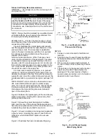
STEAM COILS — Position the steam supply connec-
tion at the top of the coil, and the return (condensate)
connection at the bottom.
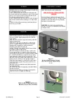
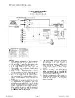
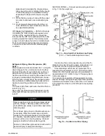
Figure 8 illustrates the normal piping components
and the suggested locations for high, medium, or low-
pressure steam coils. The low-pressure application
(zero to 15 psig) can dispense with the ¼-in. petcock
for continuous venting located above the vacuum
breaker (check valve).
Note the horizontal location of the 15-degree check
valve, and the orientation of the gate/pivot. This valve
is intended to relieve any vacuum forming in the con-
densate outlet of a condensing steam coil, and to seal
this port when steam pressure is again supplied to the
coil. It must not be installed in any other position, and
should not be used in the supply line.
For coils used in tempering service, or to preheat
outside air, install an immersion thermostat in the con-
densate line ahead of the trap. This will shut down the
supply fan and close the outdoor damper whenever the
condensate falls to a predetermined point, perhaps 120
F.
NOTE: DO NOT use an immersion thermostat to over-
ride a duct thermostat and open the steam supply
valve. For vacuum return systems, the vacuum break-
ing check valve would be piped into the condensate
line between the trap and the gate valve instead of
open to the atmosphere.
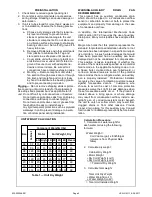
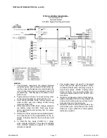
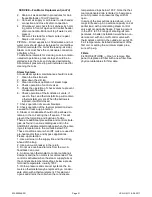
Figure 9 illustrates the typical piping at the end of every
steam supply main. Omitting this causes many field
problems and failed coils.
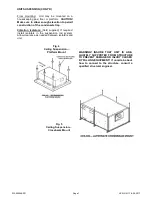
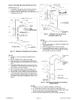
Figure 10 shows the typical field piping of multiple
coils. Use this only if the coils are the same size and
have the same pressure drop. If this is not the case, an
individual trap must be provided for each coil.
Figure 11 shows a multiple coil arrangement applied to
a gravity return, including the open air relief to the at-
mosphere, which DOES NOT replace the vacuum
breakers.
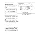
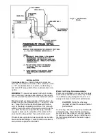
Figure 12 illustrates the basic condensate lift piping.
NOTES:
1. Flange or union is located to facilitate coil
removal.
2. Flash trap may be used if pressure differen-
tial between steam and condensate return
exceeds 5 psi.
3. Dirt leg may be replaced with a strainer. If
so, tee on drop can be replaced by a reduc-
ing ell.
4. The petcock is not necessary with a bucket
trap or any trap which has provision for
passing air. The great majority of high or
medium pressure returns end in hot wells or
deaerators which vent the air.
Fig. 8 — Low, Medium or High
Pressure Coil Piping
Steam Coil Piping Recommendations
GENERAL — Use straps around the coil casing to lift
and place the coil.
CAUTION
To prevent damage to the coil or coil headers:
Do not
use the headers to lift the coil.
Support the piping
and coil connections independently. Do not use the coil
connections to support piping. When tightening coil
connections, use a backup wrench on the coil connec-
tion stub-out.
Fig. 9 — End of Steam Supply
Main Piping Detail
Содержание HCA Series
Страница 2: ...035 000049 001 Page 2 HCA IOM 1 1 8 28 2017 THIS PAGE INTENTIONALLY LEFT BLANK...
Страница 26: ...035 000049 001 Page 26 HCA IOM 1 1 8 28 2017...
Страница 28: ...035 000049 001 Page 28 HCA IOM 1 1 8 28 2017 THIS PAGE INTENTIONALLY LEFT BLANK...
Страница 29: ...035 000049 001 Page 29 HCA IOM 1 1 8 28 2017 THIS PAGE INTENTIONALLY LEFT BLANK...


