035-000049-001
Page 13
HCA IOM 1.1 8-28-2017
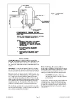
Fig. 7 — Condensate
Drain
INSTALLATION
Condensate Drain —
Install a trapped condensate
drain line at unit drain connection. HCA units have a 3/4
in. FPT condensate drain connection, or alternately a
3/4” male PVC pipe outlet for the condensate drain con-
nection.
WARNING!
To prevent excessive build-up of conden-
sate in drain pan, adequate trap clearance (trap depth)
must be provided beneath the unit as indicated in Fig. 6.
Measure maximum design negative static pressure up-
stream from the fan. Referring to Fig. 7, height “H” must
be 1” larger than the fan inlet static pressure Iinches
w.g.) at the design operating conditions. Prime enough
water in trap to prevent losing seal when starting up the
unit. After the fan is running with the design fan inlet
(negative) pressure, the elevation of the water on the
unit side of the trap will be 1” below the drain invert.
Provide freeze-up protection as required to insure relia-
ble condensate drainage. Freeze protection measures
are customer-supplied and installed.
Water Coil Piping Recommendations
Water coils are piped by connecting the supply
at the bottom and the return at the top. This is
“counterflow” piping arrangement and is nec-
essary to achieve rated thermal performance.
CAUTION!
Piping the other way
(parallel) will result in reduced thermal
performance!
Coil Venting: Water coils are not provided with
venting devices. Insure that the circulating
water system has proper air venting capability.
If vents are required at the coil, install them in
the field piping attached to the return (upper)
connection.
Содержание HCA Series
Страница 2: ...035 000049 001 Page 2 HCA IOM 1 1 8 28 2017 THIS PAGE INTENTIONALLY LEFT BLANK...
Страница 26: ...035 000049 001 Page 26 HCA IOM 1 1 8 28 2017...
Страница 28: ...035 000049 001 Page 28 HCA IOM 1 1 8 28 2017 THIS PAGE INTENTIONALLY LEFT BLANK...
Страница 29: ...035 000049 001 Page 29 HCA IOM 1 1 8 28 2017 THIS PAGE INTENTIONALLY LEFT BLANK...


