background image

Troubleshooting 


Resilience D Installation guide. © 2016, all rights reserved 

P a g e

 | 

39


Problem 

Possible Causes 

What to do 


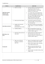
Flow icon is on and NO 
FLOW message appears 
in the numerical display 


Insufficient water 

flows from pump to 
flow sensor and cell


This is normal if there is air in the lines or for a few 

minutes at initial startup


Clean filters and strainers


Check for closed valves, pump cavitation, faulty 

pump etc'


Obstruction or lime-

scale build up in cell


Clean cell according to instruction manual (see 

"maintenance" chapter, page 31)


Flow sensor was not 

installed in the correct 
direction 


Turn flow sensor so arrow faces direction of water 

flow


Flow sensor is not fully 

threaded into the Tee 
connector 


Fully thread the Flow sensor into the Tee 

connector. Be careful not to damage the wires or 
sensors.


Cut wires or 

insufficient wire 
connections 


Check the connection to ensure proper wire 

contact


Output bar lights but 
does not reach 100% 


Output bar set too low 


Push the        button to set the output level to a 

higher setting 


Dirty cell 


Check the cell to ensure that the blades are in good 

condition and not coated with calcium buildup. 
Cleaning the cell is recommended if it is calcified or 
if the readout seems questionable. See "cell 
cleaning" in the "maintenance" chapter, page 31 


Poor connection of 

quick connectors  


Check for debris inside the connectors. Ensure that 

the quick connectors are connected 


Low pool water 

temperature 


In cold water (lower than 26 

º

C/80 

º

F the salt 

meter may indicate a lower salinity level. This is 
normal 


Not enough salt due to 

heavy rain, initial 
miscalculation etc' 


Add salt to the pool. See :"Adding salt" chapter for 

more information, page 18 


It is recommended to periodically test the salt level 

by a professional and adjust according to the 
salinity demand table in this manual, page 19 


Worn cell 


If none of the above resolves the problem the cell 

may be worn out. 


Содержание resilience D Series

Страница 1: ...Table of Contents Resilience D Installation guide 2016 all rights reserved P a g e 1 35405055 December 2016 www magen ecoenergypool com...

Страница 2: ...to all national state and local codes Improper use or installation can badly harm the unit and its surroundings When installing and using electrical equipment basic safety precautions should always be...

Страница 3: ...rials used in or around the pool and spa are compatible with salt based sanitation systems Certain materials may be susceptible to salt and chlorine damage ALWAYS ADD ACID TO WATER NEVER WATER TO ACID...

Страница 4: ...10 INSTALLATION OF DOSING ACID PUMP 10 MOUNTING THE CONTROL BOX 13 ELECTRICAL WIRING OF THE CONTROL BOX 14 WIRING THE CELL 15 WIRING THE FLOW SENSOR 15 WIRING THE TEMPERATURE SENSOR 16 WIRING THE DOSI...

Страница 5: ...D PUMP 28 ACID PIPE 28 PH CONTROL 29 pH reducing mode 29 pH reducing Auto 29 pH reducing Manual 29 Cell cleaning mode 30 Adjusting the frequency of the cleaning 30 Immediately initiating a cell cleani...

Страница 6: ...one return valve internal replacement tube 2 x 3m polyethylene tube foot filter and weight ADDITIONAL MATERIALS REQUIRED NOT SUPPLIED IN PACKAGE 1 PVC solvent cement and priming fluid 2 Hacksaw or pip...

Страница 7: ...ell Flow Sensor and dosing acid pump if purchased with the unit These assemblies are manufactured using to most advanced corrosion resistant materials that are extremely durable Installing them in an...

Страница 8: ...re less pipe length 3 On the pipe where the cell is installed mark two lines 300 mm 11 3 4 inches apart and cut out using a hacksaw or pipe cutter 4 Unscrew and remove the barrel unions i e barrel nut...

Страница 9: ...e flow and that no glue or pipe cleaner touches the paddle inside the sensor as it may cause it to jam Double check that the flow sensor operates properly by reducing the flow for five seconds and che...

Страница 10: ...ure INSTALLATION OF DOSING ACID PUMP Disconnect ALL power before work commences Open the control boxes lid to make sure the unit is turned OFF It is recommended to wear rubber or polyethylene protecti...

Страница 11: ...y a licensed electrician 7 Establish the pipe diameter you have installed and make sure you have the correct pipe saddle 50 or 63mm 8 Acid pump s pipe saddle must be installed right after the electrol...

Страница 12: ...tube to the required length this will become the suction tube Attach one end to the inlet of the acid pump left side 16 Thread the other end other suction tube through the lid of the acid container an...

Страница 13: ...OX 1 The control box must be mounted vertically on a flat surface and a minimum horizontal distance of 1 5 m 5 ft or more if local codes require from the pool 2 Select a location for your control box...

Страница 14: ...NTROL BOX CAUTION Disconnect all power supply to the main timer main power source before hardwiring the input voltage cables to the timer and control box Hardwire all accessory equipment dosing acid p...

Страница 15: ...s at the sides of the cell until they click together NOTE do not extend the original cables leading to the cell This decreases the system efficiency and will void warranty coverage WIRING THE FLOW SEN...

Страница 16: ...the acid pump socket Tighten the threaded adaptor firmly until the cable cannot be pulled out from the box The second cable marked power can be wired in two ways 1 Wire the electrical cable of the aci...

Страница 17: ...fore adding salt or operating the natural chlorine generator 3 Biguanide Pools if installing the system in a pool that has Biguanide sanitizers all Biguanide must be removed prior to system startup 4...

Страница 18: ...7 Keep the pump on to circulate the water 8 Distribute the required amount of salt evenly around the pool It will take about 8 hours for the salt to disperse evenly in the water 9 Once the salt has f...

Страница 19: ...350 300 250 200 150 100 50 0 110 440 385 330 275 220 165 110 55 0 120 480 420 360 300 240 180 120 60 0 130 520 455 390 325 260 195 130 65 0 140 560 490 420 350 280 210 140 70 0 150 600 525 450 375 300...

Страница 20: ...f needed the filter circulation pump and chlorine generator may run continuously Note inadequate filtration reduces water clarity and causes the generator to work harder Related chemistry Other chemic...

Страница 21: ...chlorine in the pool to oxidize the unwanted foreign matter Modes ON the system is ON and the circulation pump is on the system is fully operational and produces chlorine OFF the unit is OFF by manua...

Страница 22: ...turned off The main screen is active Turbo time if previously in this mode goes back to zero initialized The system measures the water s salinity and only after 1 minute displays it Make sure all read...

Страница 23: ...ress the Mode button transfers to cell cleaning pH reducing screen If the user does not have a dosing acid pump it will display NEED PUMP message After five seconds or another press on the Mode button...

Страница 24: ...nity indication Above 5500 ppm the upper bar turns on with High salt indication Above 6500 ppm the alarm salinity lamp is on Above 8000 ppm the upper salinity bar icons blink In all high salinity situ...

Страница 25: ...starts turbo operation The unit goes to 100 output for the adjusted time interval the Turbo icon starts flashing The default turbo setting is 12 hours To increase the turbo setting in 12 hour interval...

Страница 26: ...y condition i e the maximum output might be 60 so the blinking bar will show 100 setting and the solid output bar will show 60 POOL COVER FUNCTION The unique pool cover function enables the chlorinato...

Страница 27: ...ill return to the full adjusted power and turn off the high temp icon when the unit temperature drops back below 65 C 149 F LOW TEMP In case of low water temperature below 15 C 59 F the unit will disp...

Страница 28: ...recover from this state every few seconds and will automatically detect when the cable is reconnected or the salinity and or lime scale is removed NEED PUMP If the unit is attempting to reach the dosi...

Страница 29: ...UCING MODE Ensure that the circulation pump is ON then press the MODE button to go to the pH reducing modes pH reducing Auto Press the and buttons to adjust the amount of acid to infuse into the water...

Страница 30: ...MODE button to get to the CELL CLEANING AUTO mode 2 Use the buttons to adjust the cleaning level e g Level 3 LVL 0 No cleaning LVL 9 most frequent cleaning Immediately initiating a cell cleaning 1 Tu...

Страница 31: ...inder every 180 days recommended Use the buttons to decrease the number of days in steps of 10 days Once set confirm by pressing the button once MAINTENANCE Maintaining your natural chlorine generator...

Страница 32: ...n using muriatic acid vinegar takes longer 7 Safely dispose of the acid solution by pouring it into your pool 8 Rinse the cell with water hose 9 Put the O ring back in place and re install the cell in...

Страница 33: ...his operation you MUST wear rubber or polyethylene protective gloves and safety glasses It is also advisable to protect your clothes or wear dispensable ones Remove the transparent protective cover Ca...

Страница 34: ...reserved P a g e 34 Gently insert the tube back into place making sure the black bases of the tubes are tightly in their slots in the casing Return the transparent cover to its place Check for leaks...

Страница 35: ...ideal Salt is the source of the Natural Chlorine The ideal salt level to ensure maximum benefits using our system is 3500 ppm parts per million A lower concentration of salt may hinder the generator e...

Страница 36: ...and Nitrates set very high demands on chlorine most nitrates and phosphates often bring the chlorine level down to zero 0 You can have your water tested for nitrates and phosphates by a local profess...

Страница 37: ...1 9 2 1 2 2 4 Find your pool temperature in the chart below And write the corresponding temperature Factor here Temperature Factor ______________ Pool Temp 32 37 46 53 60 66 76 84 94 105 Factor 0 0 0...

Страница 38: ...chemistry stabilizer should be 60 80 ppm If low add stabilizer see Understanding the Chemistry chapter page 35 High phosphate levels Check phosphate levels at your local professional and reduce to bel...

Страница 39: ...ons Check the connection to ensure proper wire contact Output bar lights but does not reach 100 Output bar set too low Push the button to set the output level to a higher setting Dirty cell Check the...

Страница 40: ...essional If above 5000 ppm it is recommended to drain part of the pool water and refill with fresh water please check with your local pool professional prior to draining the pool Salinity far too high...

Страница 41: ...etween them Scale build up inside cell Standard occurrence that needs cleaning approximately once a month Clean cell as instructed in the maintenance chapter page 31 or purchase a dosing acid pump Che...

Страница 42: ...ree metal remover Increase circulation time if needed and clean the filter Algae May be due to low chlorine levels or a chemical imbalance Have the water tested for chemical balance including pH phosp...

Страница 43: ...air priming Acid inlet tube is not in contact with the acid above acid level Push the tube to the bottom of the acid container Observe the priming procedure as described above Pump does not run durin...

Страница 44: ...during pH reducing mode manual and automatic Check the electrical connection between the dosing acid pump and the control box and the electrical wiring from the pump to the timer main board If red led...

Отзывы: