background image

Chapter 7

Default firmware settings

7.1

Factory settings

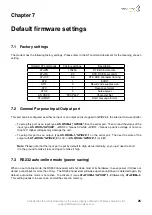
The modem has the following factory settings. Please refer to the AT command document for the meaning of each
setting.

Related AT commands

Factory settings

Description

AT+IPR

115200

DTE-DCE data rate

AT+IFC

2,2

DTE-DCE flow control

AT+ICF

3,4

DTE-DCE character framing

ATE

1

ECHO

ATQ

0

Result code suppression

ATV

1

Response format

ATS0

0

Auto answer

AT+CSCS

“PCCP437”

Character Set

AT+CMGF

1

Short message format

7.2

General Purpose Input/Output port

This port can be configured as either an input or an output and is mapped to GPIO26 in the internal micro-controller.

To setup this port as an input, type

AT+WIOM=1,"GPIO26",0

on the serial port. Then to read the status of the

input, type

AT+WIOR="GPIO26"

.

+WIOR: 0

means 0V while

+WIOR: 1

means a positive voltage of no more

than 12V. Higher voltages may damage the unit.

To setup this port as an output, type

AT+WIOM=1,"GPIO26",1

on the serial port. Then set the state of the

output with

AT+WIOW="GPIO26",0

for 0V, or

AT+WIOW="GPIO26",1

for 2.8V.

Note:

Please note that the input port is put by default to High status internally, so you just need to short

it to the ground to make it low, and open to make it high.

7.3

RS232 auto-online mode (power saving)

When on auto-online mode, the RS232 transceiver will shut down most of its hardware, to save power, if it does not
detect a valid input for more than 100

µs

. The RS232 transceiver will wake up when valid input is detected again. By

default, auto-online mode is not active. To activate it, issue

AT+WIOM=1,”GPIO22”,1,0

followed by

AT+WIOM=4

.

This setting needs to be set once, and will be saved in memory.

Confidential, the whole document is the sole property of Maestro Wireless Solutions ltd.

[email protected]

25

Содержание 100 3G

Страница 1: ...3G QUICK START GUIDE USER MANUAL VERSION 2 WWW MAESTRO WIRELESS COM EMAIL CONTACT MAESTRO WIRELESS COM TEL 852 2869 0688 FAX 852 2525 4701 ADDRESS ROOM 3603 3609 36 F 118 CONNAUGHT ROAD WEST SHEUNG WA...

Страница 2: ...2 Confidential the whole document is the sole property of Maestro Wireless Solutions ltd support maestro wireless com...

Страница 3: ...aestro Wireless Solutions Ltd in relation to this software solution or application User shall assume the entire risk of using or relying on this software solution or application In no event will Maest...

Страница 4: ...4 Confidential the whole document is the sole property of Maestro Wireless Solutions ltd support maestro wireless com...

Страница 5: ...n 21 6 1 Package 21 6 2 Interfaces 21 6 2 1 Status indicator 21 6 2 2 SMA female antenna connector 21 6 2 3 Mini USB B Female connector 22 6 2 4 15 Pin D Sub Female connector RS232 Audio 22 6 2 5 4 Pi...

Страница 6: ...d be heard for the modem s speaker output when a call is answered 27 8 5 Debug or further command using Smart Terminal as example 28 8 6 Basic operations 28 6 Confidential the whole document is the so...

Страница 7: ...stalling the modem Install the modem by qualified personnel Consult your vehicle dealer for any possible interference of electronic parts by the modem The modem should be connected to the vehicle s su...

Страница 8: ...8 Confidential the whole document is the sole property of Maestro Wireless Solutions ltd support maestro wireless com...

Страница 9: ...Molex connector but there is no analog input as on the M100evo M100 2G 4 Engineering Sample supports only passive GPS antenna final product will support both passive and active GPS antenna 5 Engineer...

Страница 10: ...10 Confidential the whole document is the sole property of Maestro Wireless Solutions ltd support maestro wireless com...

Страница 11: ...23dbm 250mA 212mA 85mA Transmission HSDPA band1 23dbm 250mA 212mA 85mA Transmission EDGE 27dbm 220mA 185mA 73mA Transmission GSM GPRS 32dbm 900MHZ 2 slots 220mA 185mA 73mA Idle RS232 USB connected 99m...

Страница 12: ...hat the installer Avoid physical contact with the Maestro 100 3G when the temperature exceeds 65 C Adds a marking on the assembly indicating that this part is hot for example showing the symbol IEC 60...

Страница 13: ...t for more information please refer to the following documentations available on our website SmartPack User Manual intelligent embedded application Maestro 100 3G AT command guide Application note Aut...

Страница 14: ...14 Confidential the whole document is the sole property of Maestro Wireless Solutions ltd support maestro wireless com...

Страница 15: ...ct an antenna with SMA male connector on the modem make sure the antenna is tightly secured Select an antenna with the right GSM frequency and an impedance of 50 incorrect antenna will affect communic...

Страница 16: ...d in the modem and it will turn on automatically The status indicator led will light when power is applied After few seconds it will blink slowly meaning the modem is registered on the network Figure...

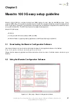
Страница 17: ...3G Coming soon M100 3G Lite without GPS and USB M100 3G Tracker supporting tracking application for GPS based alert report Q3 2013 5 1 Downloading the Maestro Configuration Software Start the web brow...

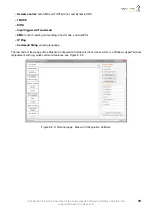
Страница 18: ...te a report of all common AT com mand that will help us solve any issue you have with the modem easily 5 Auto detect serial configuration will detect your modem serial configuration automatically thou...

Страница 19: ...g scripting language The last and not least page of the Maestro Configuration Software is the Terminal which is a Windows HyperTerminal replacement with log quick command features see Figure 5 2 3 Fig...

Страница 20: ...20 Confidential the whole document is the sole property of Maestro Wireless Solutions ltd support maestro wireless com...

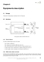
Страница 21: ...and GPS has a fix Flashing slowly modem is registered on the network and GPS doesn t have a fix Flashing rapidly modem is registered on the network and GPS has a fix 6 2 2 SMA female antenna connector...

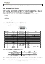
Страница 22: ...link and audio link to the modem Pin Number Name EIA designation Type Note 1 NC 2 TX Transmit Data Input 3 NC 4 MICROPHONE Input With 2VDC bias output 5 MICROPHONE Input With 2VDC bias output 6 RX Rec...

Страница 23: ...USB X Cable ACC CA41 Direct connection with standard USB for power and data channels Shielded cabled Cable length 50cm Make sure the current given to the USB connectors from computer is sufficient esp...

Страница 24: ...one for voice call Shielded cable Cable length 1 1m w connector Penta band L shape antenna ACC A11 Frequency GSM 850 900 1800 1900 2100 band Gain 6dB DIN rail mount ACC DIN DB15 to DB9 adapter OTH 004...

Страница 25: ...ile WIOR 1 means a positive voltage of no more than 12V Higher voltages may damage the unit To setup this port as an output type AT WIOM 1 GPIO26 1 on the serial port Then set the state of the output...

Страница 26: ...26 Confidential the whole document is the sole property of Maestro Wireless Solutions ltd support maestro wireless com...

Страница 27: ...ected to the modem Check if the network coverage is available Make sure that the CTS and DTR pins of the serial port are not connected together 8 3 The modem does not respond to the terminal program C...

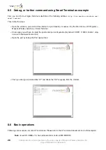
Страница 28: ...n you will have to select the good serial port configuration By default COM1 115200 8 data 1 stop none with hardware flow control Open the port by ticking the Port opened box Then you can type command...

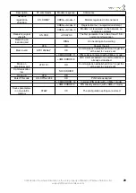
Страница 29: ...ation established Don t forget the at the end for voice call CME ERROR 11 PIN code not entered with CME 1 mode CME ERROR 3 AOC credit exceeded or a communication is already established Make an emergen...

Отзывы: