Manual
GA-60
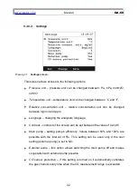
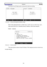
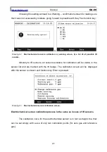
Choosing this setting will lead to a Warning confirmation screen for making sure
that the setting was not accessed by mistake, going forward is possible with they
Yes
function key:
a)
b)
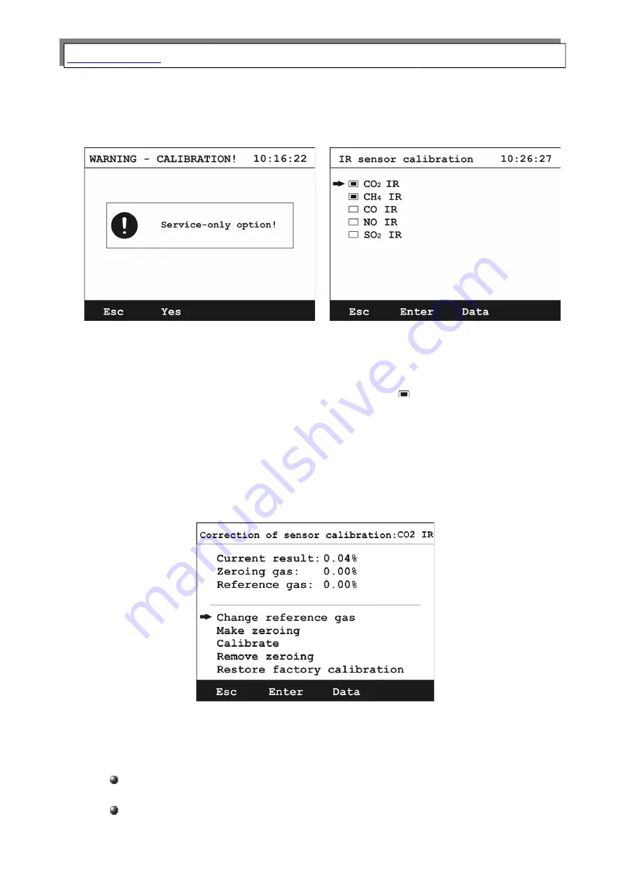
Drawing 39.
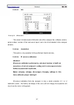
IR sensors calibration: a) warning screen, b) a list of all possible IR sensors.
IR sensors calibration screen displays a list of all sensors possible to install in the
analyser. All already present sensors are marked with a badge. After choosing the
sensor to be calibrated press the
Enter
function key to go to the calibration process.
The calibration process of the IR sensor from the analyser level is a simple
transformation (movement and/or rotation) of a factory set curve (saved in the analysers
internal memory). The transformation is based on 2 calibration points, zero gas (gas
value that the analyser zeroed the sensors) and reference gas (measured values).
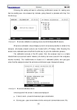
Drawing 40.
IR sensor calibration screen.
In the top part of the screen 3 values are displayed:
Current result
– presents measured gas concentration
Zeroing gas
– gas concentration for the zero point (concentration zero 0%)
38

