background image

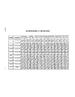
CB FREQUENCIES (11 METER BAND)

4-7


(222”) (75”) (21 1”) (69.5”) (203”) (65.5”) 

 (64.5) (199”) (63.5”) (198”) (63”) (198”) (63”)

8-1 1


(222”) (75”) (210”) (69”) (202”) (65”) (201”) (64.5) (198”) (63”) (197”) (62.5”) (197”) (62.5”)

12-15


(221”) (74.5”) (210”) (69”) (202”) (65”) (201”) (64.5) (198”) (63”) (197”) (62.5”) (197”) (62.5”)

16-19


(221”) (74.5”) (210”) (69”) (202”) (65”) (200”) (64”) (198”) (63”) (197”) (62.5”) (197”) (62.5”)

20-25


(221”) (74.5”) (209”) (68.5”) (201”) (64.5”) (200”) (64”) (197”) (62.5”) (196”) (62”) (196”) (62”)

26-29


(220”) (74”) (209”) (68.5”) (201”) (64.5”) 

 (63.5”) (197”) (62.5”) (196”) (62”) (196”) (62”)

30-34


(220”) (74”) (208”) (68”) (200”) 


 (63.5”) (196”) (62”) (196”) (62”) 

 (62”)

35-39


(219”) (73.5”) (208”) (68”) (200”) 

 (199”) (63.5”) (196”) (62”) (195”) (61.5”) 

 (61.5”)

40

27.405


(219”) (73.5”) (208”) (68”) (200”) 


 (63”) (196”) (62”) (195”) (61.5”) (195”) (61.5”)

Содержание M107C

Страница 1: ...7E L E ME N T 1 1 ME T E R MA X I MU M B E A M M1 0 7 C w w w ma c o a n t e n n a s n e t...

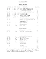
Страница 2: ...LTS ____ N03 42 5 16 LOCK NUTS ____ HARDWARE BAG 3 BE2P 7 2 BOOM TO ELEMENT MOUNTS ____ BG2P 4 GUY MOUNTS ____ N18 6 5 16 EYEBOLTS WITH 12 NO1 NUTS ____ HARDWARE BAG 4 W58P 16 5 8 EXTRUDED ALUMINUM CL...

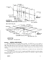
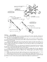
Страница 3: ...107C may be used vertically or horizontally These instructions and FIGURES 2 through 4 show the correct assembly instructions It is highly recommended that rope be put in the elements to prolong their...

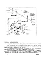
Страница 4: ...port VO3P at the boom center using 2 U bolts saddles and hardware as shown in Figure 2A Be sure to slip the 2 U bolt for attaching the guy support over the boom before securing the mast plate POlP Sli...

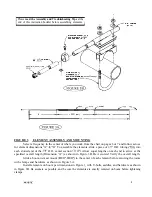
Страница 5: ...cross for element dimensions A B To assemble the elements slide a piece of l 2 O D tubing TOl into each slotted end of the 5 8 O D center section Tl 1P Allow equal lengths on each end to arrive at the...

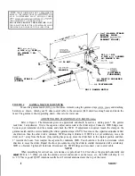
Страница 6: ...r EGl on each 609M 24 guy cable leaving only 304M 12 between eyebolt and egg insulator Wrap and cut off excess Using the remaining 2 108M 83 guy cable thread one end through the top egg insulator of t...

Страница 7: ...200 64 198 63 197 62 5 197 62 5 20 25 27 205 27 245 5 613M 1 686M5 308M 1 739M 5 105M 1 625M 5 080N 1 625M 5 003M 1 578N4 978M 1 574M 4 978M 1 574M 221 74 5 209 68 5 201 64 5 200 64 197 62 5 196 62 19...

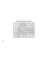
Страница 8: ...ECTOR 4 699M 185 3rd DIRECTOR 4 699M 185 4th DIRECTOR 4 699M 185 5th DIRECTOR 4 699M 185 INE cw MHz 28 100 MHz B A B 1 496M 5 334M 1 547M 6 7 210 6 9 1 574M 5 080M 1 625M 62 200 6 4 1 485M 4 876M 1 52...

Страница 9: ...INNER CABLE DIMENSIONS CABLE LENGTH DIMENSIONS OUTER CABLE DIMENSIONS 24 24 90 70 n 24 CABLE LENGTH Y i DIMENSIONS Ml07C...

Страница 10: ...a starting point The gamma match has 2 adjustments First is the capacitor adjust and second is the slider adjust Connect a SWR bridge coax between your transmitter and the antenna and check the SWR I...

Страница 11: ...e m b l y C o n t a c t y o u r l o c a l i n s t a l l e r i f c o n s u l t a t i o n o r a s s i s t a n c e i s r e q u i r e d A l l t o w e r a n d a n t e n n a i n s t a l l a t i o n s s h o...

Отзывы: