background image


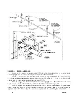
CENTER 

 SECTION 

VERTICAL 

 COUPLER 

S U P P O R T  

--BOON-TO-MST 


CENTER 

 SECTION 


 COUPLERSECTION 

2' U-BOLTS 

2' SADDLES 


 NUT 

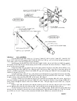
FIGURE 2

BOOM ASSEMBLY

First mark the center of the boom coupler 

 then slide the unslotted ends of the center boom

sections 

 over each end of the coupler so they butt at the center mark.

Attach the boom-to-mast plate (PO 

 and the vertical guy support 

 at the boom center using

2” U-bolts, saddles and hardware as shown in Figure 2A. Be sure to slip the 2” U-bolt for attaching the guy
support over the boom before securing the mast plate 

Slide the 

 ends of the intermediate boom sections 

 6” into the slotted ends of the center

boom sections. Secure with 2” U-bolts, saddles and hardware as shown in Figure 2B.

Slide the 

 ends of the end booms sections (T28)   into the slotted ends of the intermediate

boom section and secure in the same manner as above. The overall length of the boom should be

approximately 443”. If not, adjust the end sections equally until the overall length is at least 443”.

3

Содержание M107C

Страница 1: ...7E L E ME N T 1 1 ME T E R MA X I MU M B E A M M1 0 7 C w w w ma c o a n t e n n a s n e t...

Страница 2: ...LTS ____ N03 42 5 16 LOCK NUTS ____ HARDWARE BAG 3 BE2P 7 2 BOOM TO ELEMENT MOUNTS ____ BG2P 4 GUY MOUNTS ____ N18 6 5 16 EYEBOLTS WITH 12 NO1 NUTS ____ HARDWARE BAG 4 W58P 16 5 8 EXTRUDED ALUMINUM CL...

Страница 3: ...107C may be used vertically or horizontally These instructions and FIGURES 2 through 4 show the correct assembly instructions It is highly recommended that rope be put in the elements to prolong their...

Страница 4: ...port VO3P at the boom center using 2 U bolts saddles and hardware as shown in Figure 2A Be sure to slip the 2 U bolt for attaching the guy support over the boom before securing the mast plate POlP Sli...

Страница 5: ...cross for element dimensions A B To assemble the elements slide a piece of l 2 O D tubing TOl into each slotted end of the 5 8 O D center section Tl 1P Allow equal lengths on each end to arrive at the...

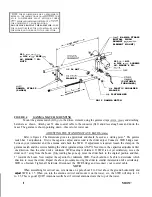
Страница 6: ...r EGl on each 609M 24 guy cable leaving only 304M 12 between eyebolt and egg insulator Wrap and cut off excess Using the remaining 2 108M 83 guy cable thread one end through the top egg insulator of t...

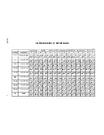
Страница 7: ...200 64 198 63 197 62 5 197 62 5 20 25 27 205 27 245 5 613M 1 686M5 308M 1 739M 5 105M 1 625M 5 080N 1 625M 5 003M 1 578N4 978M 1 574M 4 978M 1 574M 221 74 5 209 68 5 201 64 5 200 64 197 62 5 196 62 19...

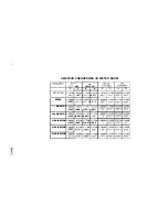
Страница 8: ...ECTOR 4 699M 185 3rd DIRECTOR 4 699M 185 4th DIRECTOR 4 699M 185 5th DIRECTOR 4 699M 185 INE cw MHz 28 100 MHz B A B 1 496M 5 334M 1 547M 6 7 210 6 9 1 574M 5 080M 1 625M 62 200 6 4 1 485M 4 876M 1 52...

Страница 9: ...INNER CABLE DIMENSIONS CABLE LENGTH DIMENSIONS OUTER CABLE DIMENSIONS 24 24 90 70 n 24 CABLE LENGTH Y i DIMENSIONS Ml07C...

Страница 10: ...a starting point The gamma match has 2 adjustments First is the capacitor adjust and second is the slider adjust Connect a SWR bridge coax between your transmitter and the antenna and check the SWR I...

Страница 11: ...e m b l y C o n t a c t y o u r l o c a l i n s t a l l e r i f c o n s u l t a t i o n o r a s s i s t a n c e i s r e q u i r e d A l l t o w e r a n d a n t e n n a i n s t a l l a t i o n s s h o...

Отзывы: