Mackworth SA400 Скачать руководство пользователя страница 23


995565 – Revision A 


Page 23 of 38 


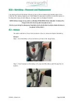
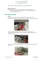
Step 5 – Pull the Pin out from the bottom fixing to release the Actuator.  


Step 6 – Remove the Actuator and rest the Upper Assembly on the Stand Aid. 

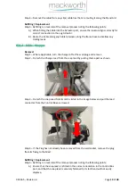
Refitting / Replacement 

Step 7 - Refitting is a reversal of the removal process noting the following point: 

A)


Ensure the Actuator is fitted in the correct orientation. With the LIANK Specification 
label facing towards the Mast.  
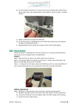
B)


Ensure the Nuts are tight and secure the Actuator, do not over tighten as this will 
bend the framework and will affect the functioning of the Actuator. 
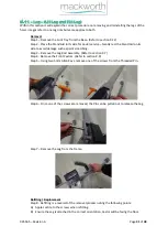
C)


Apply Loctite 243 to the Actuator Screw Pins before fitting. 


Содержание SA400

Страница 1: ...Doc No 995565 Revision of document A Rev Date 26 04 2021 SA400 Stand Aid Service Manual...

Страница 2: ...ton not working 12 8 7 Stand Aid Leg Actuator is not responding 13 8 8 Stand Aid has Power but does not respond to Handset commands 13 8 9 Stand Aid doesn t respond to the correct Handset commands 14...

Страница 3: ...end user 2 0 Safety Precautions Read and understand this manual in its entirety before servicing the Mackworth SA400 Stand Aid Mackworth authorised personnel must complete the Full and Interim service...

Страница 4: ...h service See User Manual for cleaning details Check all main nuts and bolts to see if they are loose if so tighten accordingly Check all pivot points for wear Ensure all Hand Knobs are functioning as...

Страница 5: ...tions correctly Foot Tray Ensure the Foot Grips are still applied and undamaged Inspect the Foot Tray for any permanent deformation or fatigue Ensure no cracks are present and the Foot Tray is attache...

Страница 6: ...he Upper Assembly using lift straps 8 Raise the Weight 2 3 the lifting range Be vigilant for unusual noises while raising the weight 9 Deactivate the brakes and close the legs using the handset 10 Dri...

Страница 7: ...m Allen Key 4mm Allen Key x2 5mm Allen Key x2 6mm Allen Key x2 8mm Allen Key 17mm Spanner x2 17mm Ratchet Spanner Flat Head Screwdriver Circlip Pliers Pocket Knife Equipment Required Marker Pen Cloth...

Страница 8: ...laws for disposal within the community the device is being used within If there is any uncertainty of the below guidelines contact your local authorities to determine the proper method of disposal of...

Страница 9: ...Assembly 107903 RH Leg Assembly 107260 Foot Tray Assembly 107915 Lift Actuator Kit 107308 Knee Pad Assembly 107901 Front Castor Kit Pair 107902 Rear Castor Kit Pair 107213 Mackworth SA400 Base Assemb...

Страница 10: ...tivated 2 Check the Handset is correctly connected to the correct control box port 3 Check the Handset lead is not damaged e g cuts and breaks 4 Check to see if the battery is out of charge and requir...

Страница 11: ...t 4 Connect the Battery correctly to the Control Box as shown in section 9 2 4 5 Replace the Battery see section 9 1 6 Replace the Control Box see section 9 3 7 See section 9 2 4 on Charger Lead repla...

Страница 12: ...ift Actuator replacement 2 See section 9 3 for guidance on Control Box replacement 8 5 Stand Aid is functioning but LCD and or LED is inactive Attempt to raise lower the Stand Aid with the handset the...

Страница 13: ...Replace the Handset See section 9 2 1 for Handset commissioning 6 See section 9 8 for guidance on Leg Actuator replacement 7 See section 9 3 for guidance on Control Box replacement 8 8 Stand Aid has...

Страница 14: ...ide 1 Check the Lift Actuator and Leg Actuator power cables are connected to the correct port in the Control Box Action Guide 1 Re route the power cables to the correct ports in the Control Box See se...

Страница 15: ...0 NOTE Before carrying out any work on a Mackworth SA400 Stand Aid remember to remove the charger lead and remove any external power source Prior to any servicing the Emergency Stop Button on the Cont...

Страница 16: ...ll explain the correct procedure on removing refitting the Cables for servicing procedures or replacement 9 2 1 Cables Handset Removal Step 1 Remove the Handset connecter from the Control Box by pulli...

Страница 17: ...ove the Jack End of the Cable which ports the Control Box by pulling downward This is the middle Control Box Port as shown in the image Step 2 Release the cable from the Actuator by turning the lock m...

Страница 18: ...the actuator port 9 2 3 Cable Leg Actuator Removal Step 1 Remove the Jack End of the Cable which ports the Control Box by pulling downward This is the port on the right hand side of the Control Box a...

Страница 19: ...Step 1 Where Applicable turn the charger off at the wall plug and remove Step 2 Detach the Charger lead from the snap lead by pulling them apart as shown Step 3 Detach the snap Lead from its latch cir...

Страница 20: ...p 2 Remove all the Cabling leads from the Control Box Refer to section 9 2 Step 3 Use a 3mm Allen Key to remove the Screw fixing the Control Box to the Bracket Step 4 Lift the Control Box from its pos...

Страница 21: ...procedures or replacement Removal Step 1 Remove the Battery refer to section 9 1 Step 2 Remove the Cables Leads from the Control Box refer to section 9 2 Step 3 Remove the Control Box refer to section...

Страница 22: ...See section 9 2 2 Step 2 Using two 4mm Allen Keys remove one of the screws and washer from the pin at the Top Actuator fixing point Step 3 Pull the Pin out from the top fixing to release the top end o...

Страница 23: ...efitting is a reversal of the removal process noting the following point A Ensure the Actuator is fitted in the correct orientation With the LIANK Specification label facing towards the Mast B Ensure...

Страница 24: ...e the Lift Actuator Cable See section 9 2 2 Step 2 Remove the Lift Actuator See section 9 5 Step 3 Using two 6mm Allen Keys remove one of the Bolts securing the Upper Assembly to the Frame Step 4 Usin...

Страница 25: ...g point A Ensure the threaded boss is placed within the Upper Assembly when fitting B Ensure Loctite 243 is applied to both bolts when fixing the Upper Assembly C When fitting the Upper Assembly ensur...

Страница 26: ...our Bolts circled in the image below using a 6mm Allen Key Step 4 The Leg Rods can be removed from the product Refitting Replacement Step 5 Refitting is a reversal of the removal process noting the fo...

Страница 27: ...on its side for easier service Step 3 Remove the Leg Rod Assembly from the Base Refer to section 9 7 Step 4 Remove the Bolt attaching the Leg Actuator to the Base Pivot Point using a 17mm Spanner and...

Страница 28: ...asher shown Step 8 To remove the Pivot Plate and Actuator unscrew the bolt as shown and grab the Spacer Refitting Replacement Step 9 Refitting is a reversal of the removal process noting the following...

Страница 29: ...ling the Front Castor for servicing procedures or replacement Removal Step 1 Remove the Foot Tray from the Base Refer to section 9 12 Step 2 Place the Stand Aid in its side for easier service Gently r...

Страница 30: ...and Aid in its side for easier service Gently rest the Stand Aid on its side to avoid damage such as paint scratching Step 3 To release the Rear Castor place a 6mm Allen Key into the bolt and remove t...

Страница 31: ...to avoid damage such as paint scratching Step 3 Remove the Leg Rod Assembly Refer to section 9 7 Step 4 Remove the Front Castors Refer to section 9 9 Step 5 Using two 5mm Allen Keys remove one of the...

Страница 32: ...the Foot Tray for servicing procedures or replacement Removal Step 1 Foot Tray is attached to the Base by the Pins circled in the image below Where applicable use circlip pliers to remove the retainin...

Страница 33: ...anners remove a nut from either side of the Knee Pad Attachment Bar Ensure to grab the Nylon Washer circled Step 2 Slide the Threaded Bar through the Inner Knee Pad Pivot Assembly to remove the Knee P...

Страница 34: ...the Bolt Step 6 Remove the Outer Knee Pad Pivot Assembly Take note which hole position the second plunger was aligned with Refitting Replacement Step 7 Refitting is a reversal of the removal process n...

Страница 35: ...sers preferred hole position shown below D When reattaching the Knee Pad to the Threaded Bar ensure the Washers are fitted in the correct positions Nut washer nylon washer Knee Pad nylon washer Inner...

Страница 36: ...lly off the Base to remove Step 4 Remove the Foot Tray from the Base See section 9 12 Step 5 Place the Base on its side for easier service Step 6 Remove the Rear Castors See section 9 10 Step 7 Remove...

Страница 37: ...ol Box See section 9 2 Step 3 Remove the Control Box from the Mast See section 9 3 Step 4 Remove the Attachment Bracket from the Mast See section 9 4 Step 5 Remove the Lift Actuator from the Stand Aid...

Страница 38: ...ntained in this assembly and installation manual no liability can be accepted by Mackworth for any errors or omissions Mackworth operates a policy of continuous improvement Specifications and other da...

Отзывы: