


from the control.
Figure 13 - USB Port
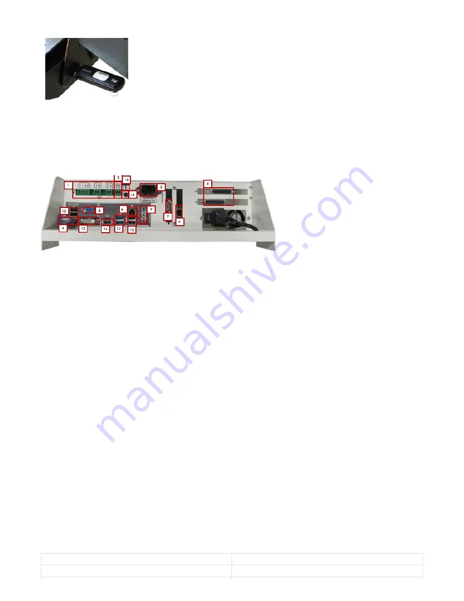
Below is a diagram of all the different ports on the control with a brief description of each.
Figure 14 - Control Port Diagram
1. Power Board
Three power supplies (24VDC, 12VDC, & 5VDC) for low power applications.
2. Power Cable
110VAC-220VAC power for the control.
3. PC Start
To remotely start the control connect these two pins together with a momentary push button switch.
4. PS2 Port with USB Converter
This is used for the mouse.
5. Parallel Ports (Optional)
These are used to communicate with some breakout boards
6. Ethernet Ports
These ports are used to connect to local Ethernet networks and motion controllers.
7. Serial Port
This can be used for any application. Many of our systems use it to communicate with a PLC.
8. VGA Monitor Connector
This is used to connect the control to a monitor with a standard VGA cable.
9. Audio
These are the standard audio inputs and outputs.
10. USB Ports
These ports are used for the keyboard, mouse, operator panel, file transfer, and more.
11. Fan Connectors
These connectors supply 12VDC for two small fans.
12. USB 3.0 Ports
These ports can be used like all the other USB ports. They are higher performance and have a much higher data
transfer speed.
13. DVI
Optional monitor connection
14. HDMI Port
Optional monitor connection
15. Secondary Power Button
Below is the specification for a standard X15-250 CNC control.
It em
Specif icat io n
Powe r Source
AC 115VAC – 220VAC 50/60 Hz
3 Computer Port Diagram
4 Specification


