background image

©Copyright MAC Instruments 2005.  All Rights Reserved. 

MAC155 Rev. 12 


Pg 9 


INSTALLATION 

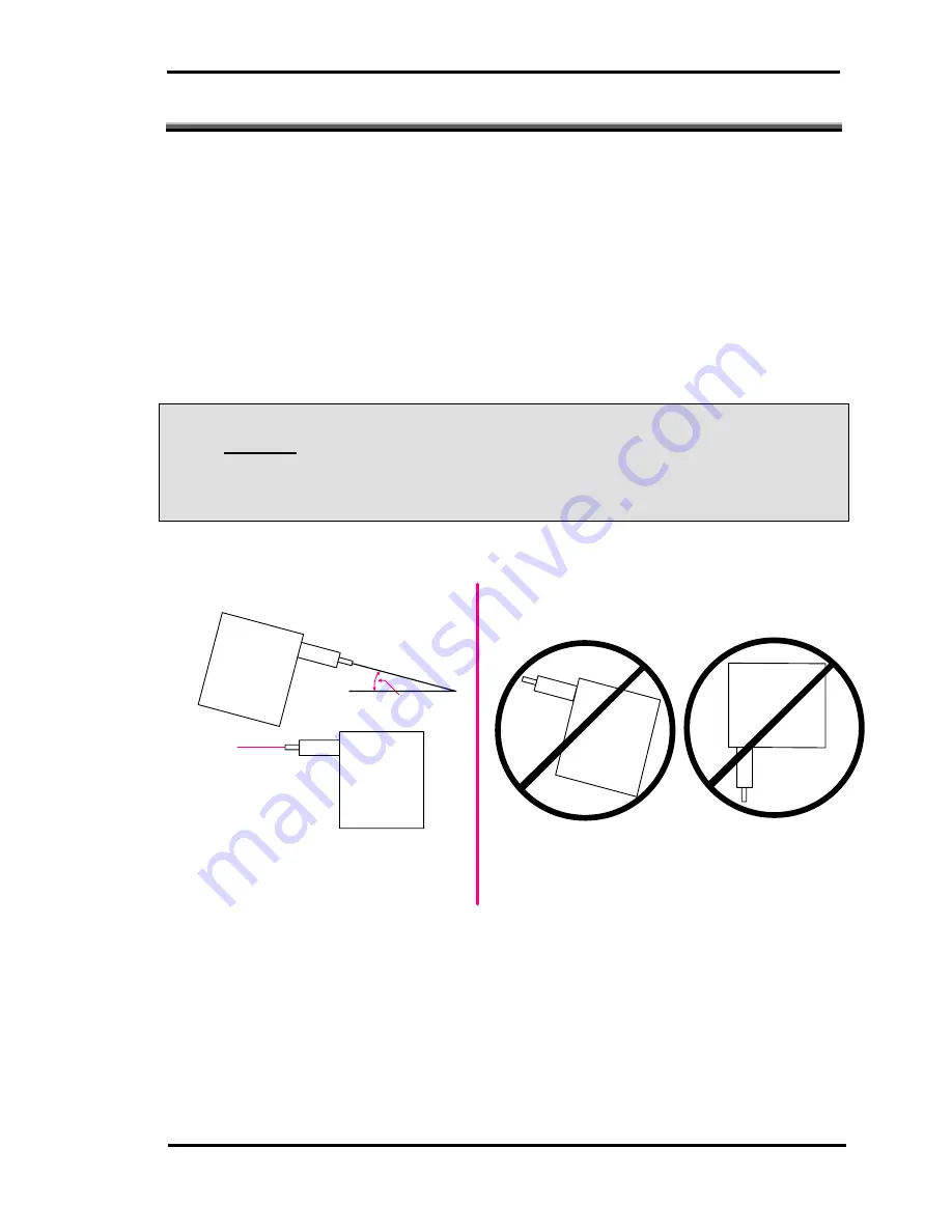
Installation of the MAC155 Probe is relatively simple. It is mechanically 

mounted to the instrumentation port using a mounting adapter. TheMAC155 

Probe must be mounted in a horizontal position (-0°, +15°), refer to Figure 4. 

Electrical connections are made through two waterproof (NEMA 4 – IP 65) 

connectors. Although the MAC155 Probe is suitable for outdoor installation, it 

should not be mounted where it would be exposed to direct sun light, or high 

ambient temperature; unless the case cool option is used. 

L

DO NOT

 install the MAC155 Probe in a location where it will be exposed 

to direct sun light or high ambient temperature; unless the case cool option is 
used. 


MAC155B

MAC155

B

M

A

C

155B

LEVEL

YES

MAC155

B

+15

NO

LEVEL


Figure 4 – MAC155 Probe Mounting 

Содержание MAC155L

Страница 1: ...Copyright MAC Instruments 2005 All Rights Reserved MAC155 Rev 12 Instruction Manual for the MAC155L MAC155H Moisture Analyzer...

Страница 2: ......

Страница 3: ...Copyright MAC Instruments 2005 All Rights Reserved MAC155 Rev 12 Instruction Manual for the MAC155L MAC155H Moisture Analyzer...

Страница 4: ......

Страница 5: ...5 CASE COOL 6 FILTER BLOW BACK 6 INSTALLATION 9 MOUNTING ADAPTER 11 WALL MOUNT REMOTE SAMPLING PROBE OPTION 12 PROBE WIRING 12 PROBE JUNCTION BOX 15 MAC155 PROBE JUNCTION BOX OPTION 15 MAC155 CONTROL...

Страница 6: ...S 45 M1 Test of sample gas flow path 45 M2 Test of reference gas flow path 46 M3 Sampling pump test 47 M4 Calibration pump test 48 Electrical Tests Controller 48 Power Supplies 50 LED Status Indicator...

Страница 7: ...9 PLC INTERFACE OUTPUTS 69 PLC INTERFACE INPUTS 71 ETHERNET CONTROLLER OPTION 72 INITIAL SETUP 72 Hardware Requirements 72 Communication with Controller 72 CONTROLLER LOGIN 72 NORMAL OPERATION SCREEN...

Страница 8: ...mpling Probe Mounting Hole Layout 97 Probe Assembly 99 Controller Outline 101 Controller Assembly 120V 103 Probe Main Board Layout 105 Controller Main Board Layout 107 PLC Interface Wiring Diagram 109...

Страница 9: ...Copyright MAC Instruments 2005 All Rights Reserved MAC155 Rev 12 Pg v 127...

Страница 10: ...Probe Connectors 18 Figure 12 Controller PE GND stud 19 Figure 13 MAC155 0 5V Operation 20 Figure 14 Water Level Sensor Location 24 Figure 15 Water Filling Flushing Kit 25 Figure 16 Filling Water Tan...

Страница 11: ...lect 61 Figure 43 Forced Analog Output Menu 62 Figure 44 Force Calibration Pump ON Menu 63 Figure 45 Force Blow Back Sol ON Menu 63 Figure 46 Forced Case Heater Menu 64 Figure 47 Force Cond Temp to 10...

Страница 12: ...ime Setup Menu 83 Figure 64 MAC155 Time Setup Menu 83 Figure 65 MAC155 Time Setup Menu 84 Figure 66 MAC155 Time Setup Menu 85 Figure 67 Modbus 8bit Input Word 87 Figure 68 Modbus 8bit Output Word 87 T...

Страница 13: ...Copyright MAC Instruments 2005 All Rights Reserved MAC155 Rev 12 Pg ix...

Страница 14: ...t with surface could cause burns Risk of electric shock High voltage is present which could cause electric shock Consult Service Manual Read manual before performing any operation Protective Conductor...

Страница 15: ...Copyright MAC Instruments 2005 All Rights Reserved MAC155 Rev 12 Pg xi...

Страница 16: ......

Страница 17: ...onitored and a controller which is typically located in a control room The MAC155 has multiple ranges which are user selectable using the display and pushbuttons on the controller It is necessary to d...

Страница 18: ...s approximately 17 ounces 500mL of distilled water Under normal operating conditions the water will last for over a year It is recommended however that the reservoir be drained and re filled at least...

Страница 19: ...o points The calibrator consists of the following pieces of hardware Water Tank Condenser Calibration Valve Calibration Pump WATER TANK The water tank holds a supply of distilled water that is used to...

Страница 20: ...by volume level CALIBRATION VALVE The calibration valve is normally closed when the instrument is in the RUN mode The calibration valve opens in the CALIBRATION OR CALIBRATION CHECK modes to allow the...

Страница 21: ...nsion tube is to draw the sample atmosphere at a point well away from the wall of the stack or duct The 3 foot 0 9 meter extension tube can be cut to any desired length Figure 2 Extension Tube cut to...

Страница 22: ...should be implemented This option requires the user to supply a source of 10 psi 69kPa clean dry and oil free air into the 0 170 barbed hose fitting on the MAC155 case see figure 3 FILTER BLOW BACK Th...

Страница 23: ...ed Air Input It is required to provide clean dry instrument air for the compressed air input Failure to do so may result in damage to the moisture sensor which is not covered under the warranty LWhen...

Страница 24: ...MAC155 Rev 12 Copyright MAC Instruments 2005 All Rights Reserved Pg 8...

Страница 25: ...connections are made through two waterproof NEMA 4 IP 65 connectors Although the MAC155 Probe is suitable for outdoor installation it should not be mounted where it would be exposed to direct sun lig...

Страница 26: ...MAC155 Rev 12 Copyright MAC Instruments 2005 All Rights Reserved Pg 10 Figure 5 Typical MAC155 Probe Installation...

Страница 27: ...ng cap is to cover the hole in the mounting adapter if the MAC155 Probe is removed The clamp is used to hold either the sealing cap or the MAC155 Probe in place A Teflon gasket is also provided with t...

Страница 28: ...hole layout for mounting the probe The probe should be mounted to the wall or panel using 4 fillister head screws PROBE WIRING The MAC155 is powered by a nominal 120 VAC 50 60 HZ 3A max power source T...

Страница 29: ...nded termination point The PE stud should be terminated before any other connections to the unit are made with a 14 gauge 2 5mm2 or larger wire It is not permitted to terminate more than one wire on t...

Страница 30: ...truments 2005 All Rights Reserved Pg 14 Maximum length of Wires One Way Wire Size AWG Nom Size mm2 150 Feet 12 4 mm2 240 Feet 10 6 mm2 400 Feet 8 10 mm2 600 Feet 6 16 mm2 1000 Feet 4 25 mm2 Table 1 DC...

Страница 31: ...ective to mount DC power supplies near the MAC155 probe In some cases it is also desirable to obtain AC power from a source close to the MAC155 probe rather than running it from the MAC155 Controller...

Страница 32: ...measuring approximately 7 5 X 7 5 X 2 5 The 6 conductor I O cable connects between the controller and the terminal strip in the fiber optic converter junction box The I O cable supplies 15V DC power...

Страница 33: ...nserted into the adapter by placing the gasket over the probe barrel and then inserting the probe barrel into the mounting flange adapter Insertion into the mounting flange adapter requires an assista...

Страница 34: ...troller I O Pin Designations PROBE TO CONTROLLER WIRING Using the supplied cables connect the controller to the probe The rear of the controller provides the appropriate connections The wiring to the...

Страница 35: ...panel of the controller via a menu and pushbuttons Refer to the Setup section for the controller 0 TO 10V OR 0 TO 5V OPERATION The current loop configuration provides a high degree of immunity from in...

Страница 36: ...NTENANCE MODE CONTACT The maintenance mode relay contact Normally Closed is wired to terminals on the rear of the controller When power is applied to the MAC155 this contact opens The contact can also...

Страница 37: ...circuit must match the output of the solid state relay contacts RS485 COMMUNICATIONS The RS 485 port is provided on the rear of the controller to implement communications to external devices The exte...

Страница 38: ......

Страница 39: ...the MAC155 is not in operation when the monitored equipment is in operation remove the MAC155 from the mounting tube and seal the mounting tube with the sealing cap provided WATER TANK PREPARATION Be...

Страница 40: ...ensor If the water level falls below a minimum level the Low Water alarm will be activated L The Low Water alarm signal indicates that service to the water tank is required WATER FILLING FLUSHING KIT...

Страница 41: ...on a level surface and open the cover Remove the plug by releasing the retention lever and pulling the plug straight out Place the drip prevention tube over the fill port Use the funnel and fill the...

Страница 42: ...ter from the tank Draining is performed by first removing the fill plug then disconnecting the tubing that comes from the tank to the calibration pump at the calibration pump end and connecting the si...

Страница 43: ...Copyright MAC Instruments 2005 All Rights Reserved MAC155 Rev 12 Pg 27 Figure 17 Draining Water Tank Siphoning Pump...

Страница 44: ...d from the ground pin of the power connector to a proper earth ground Also check that the AC voltage is correct 120 VAC 50 60 HZ or 240 VAC 50 60 Hz and is connected to the correct pins of the power c...

Страница 45: ...pump will stop running and there will be no status messages displayed on the screen Figure 18 Normal Display STATUS INDICATORS There are nine LED s on the main board that indicate the status of variou...

Страница 46: ...indicates power off Note case heater is an option ON OR OFF Case Cool Power to case cool solenoid status ON indicates power on OFF indicates power off Note case cool is an option ON OR OFF Water Leve...

Страница 47: ...155 can be placed into a calibration check once every 24 hours The time this function will activate is determined by the setting in the controller A time setting of 0 00 will disable the automatic cal...

Страница 48: ...MAC155 Rev 12 Copyright MAC Instruments 2005 All Rights Reserved Pg 32 Notes...

Страница 49: ...thin the MAC155 Probe that may require maintenance or even replacement from time to time FILTER EXTENSION TUBE INSTALLING THE FILTER 1 Remove the filter cover 2 Remove the compression spring 3 Slide t...

Страница 50: ...n should be used This option automatically cleans the filter by blowing user supplied compressed air in the reverse direction through the filter once per day during the calibration check In order to m...

Страница 51: ...ed they should not be blown from the filter with compressed air but should instead be allowed to evaporate in a well ventilated area far removed from sources of ignition If compressed air were used a...

Страница 52: ...should be drained flushed and refilled at least once per year Read the OPERATION section in this manual for information about filling the tank When it is time to re fill the water tank proceed as fol...

Страница 53: ...revolution every 4 seconds This low speed combined with the sturdy construction of the pump assures a long life A new pump can produce a vacuum of approximately 8 psi 55 kP The pump will perform prope...

Страница 54: ...e sampling pump to assure that the sensor is flooded with the calibration gas The calibration pump can be tested in the same way as the sampling pump The pump will work properly as long as it can main...

Страница 55: ...v 12 Pg 39 PERISTALTIC PUMP TUBING REPLACEMENT Figure 24 Peristaltic Pump stand in Tubing 6 Remove the two screws holding the plastic head assembly and remove the assembly from the motor Figure 25 Per...

Страница 56: ...quired and remove the old tubing by pulling the white cam wheel and tubing out of the plastic housing Figure 26 Peristaltic Pump Housing Figure 27 Disassembled Peristaltic Pump Housing 8 Wrap the new...

Страница 57: ...ing Insert the two screws through the holes in the housing and place the two black rubber washers over the ends of the screws to hold them in place 10 Mount the housing onto the motor Note that the fl...

Страница 58: ...MAC155 Rev 12 Copyright MAC Instruments 2005 All Rights Reserved Pg 42...

Страница 59: ...n be thought of as the Moisture Analyzer Additional equipment in the MAC155 Probe is there only for checking the calibration of the Moisture Analyzer The equipment that is used to check the calibratio...

Страница 60: ...t containing tubing fittings and tubing is included with the MAC155 Probe to facilitate connections of the test gauge to the MAC155 Probe Do NOT use a liquid filled manometer when testing differential...

Страница 61: ...oved and blown out as described in the maintenance section of this manual The silicone rubber tubing running from the sensor module to the sampling pump should be removed and tested for blockage Repla...

Страница 62: ...h The components in the reference gas flow path are the calibration pump the water tank the condenser the calibration valve and the barrel It is highly unlikely that the flow path for the reference ga...

Страница 63: ...M3 If the calibration pump is working properly and the water tank tubes and fill plug are not leaking the reference gas must flow into the barrel when the pump runs M3 Sampling pump test A new pump ca...

Страница 64: ...ent and place it in the calibration check mode Note the reading on the vacuum gauge If it is at least 2 psi vacuum the calibration pump is operating properly 4 Disconnect electrical power disconnect t...

Страница 65: ...v 12 Pg 49 Figure 28 AC Input Fuse Location Other fuses located on the back of the controller are for the 120V AC power and the 15V DC power feeding the probe Figure 29 Probe Fuse Location on Controll...

Страница 66: ...o supplies DC power to the MAC155 probe in addition to the remaining 15V supply Each power supply has a green LED which indicates if voltage is present on the output The power supplies have a current...

Страница 67: ...ne 9 LED s to aid in diagnosing potential problems with the MAC155 probe The probe receives 120V AC power and 15V DC power from the MAC155 controller Fuses for these lines are located on the back of t...

Страница 68: ...here is no LED indicator to represent this supply due to the nature of the low current output available Test points are available for the 5V analog supply at the tope edge of the main board just below...

Страница 69: ...ature is below 45 F 7 C If the probe is equipped with the case heater option 120V AC power is applied to the case heater when ever the LED is ON Filter Blow Back The Blow Back LED comes on for 2 sec w...

Страница 70: ...MAC155 Rev 12 Copyright MAC Instruments 2005 All Rights Reserved Pg 54...

Страница 71: ...ntroller s display To enter the menu system press the lower pushbutton indicated by a black cap Upon pressing this button the controller will enter the general menu display Three different menu select...

Страница 72: ...the clock one minute If the minute pushbutton is continuously pressed the clock will auto increment 1 minute approximately of a second Setting the Hours Pressing the Red pushbutton will increment the...

Страница 73: ...per 24hr time period Set the Auto CalCheck Time using the same method as described in the Time Set Menu Setting a time of 0 00 will disable the Auto CalCheck Figure 32 Auto CalCheck Time Set Menu DISP...

Страница 74: ...s two different current loop scales Scale 1 4 20mA Scale 2 0 20mA The default level is 4 20mA PROBE MBV RANGE SELECTION Figure 35 Probe MBV Range Selection Menu The MAC155 L menu provides two differen...

Страница 75: ...wer must be removed from the MAC155 and then reapplied MAINTENANCE RELAY SET UP Figure 36 Maintenance Relay Setup Menu This menu is to enable the maintenance contacts to close during calibration and c...

Страница 76: ...ting the MODBUS RTU slave address for the MAC155 After pressing enter the following screen will appear Figure 39 MODBUS address setup 1 Press the INCREMENT or DECREMENT buttons to select the 1st digit...

Страница 77: ...Option Figure 41 MODBUS RTU Baud rate setup This menu item is used to set the desired baud rate for MODBUS RTU communications Pressing ENTER will bring up the following display Figure 42 MODBUS Baud...

Страница 78: ...Range 4 0 mA 0 20 8 0 mA 25 40 12 0 mA 50 60 16 0 mA 75 80 20 0 mA 100 100 Example using above table a 15 full scale instrument 50 of full scale is 7 5 MBV This output signal will be present on the an...

Страница 79: ...at the previously set value until the enable button is pressed or until the diagnostic menu is exited MANUAL CAL PUMP OPERATION Figure 44 Force Calibration Pump ON Menu Pressing the Enable pushbutton...

Страница 80: ...EXIT pushbutton is disabled until the DISABLE button is pressed MANUAL CASE HTR OPERATION Figure 46 Forced Case Heater Menu If the MAC155 Probe is equipped with the case heater option the case heater...

Страница 81: ...the EXIT button before the DISABLE button will result in no change in the display since the EXIT button is disabled during this forced condition FORCE COND TEMP 130 Figure 48 Force Cond Temp to 130 Me...

Страница 82: ...eriod of 12 minutes When the calibrator has finished generating the low and high calibration points the new calibration values are stored in the MAC155 Probe and then returns to normal operation Verif...

Страница 83: ...generate a calibration gas stream of 80 of full scale for a period of 11 minutes At the end of that period the MAC155 Probe returns to the normal mode The calibration of the probe is left unchanged MA...

Страница 84: ...nd six outputs are available to interface to a PLC LEDs indicate if signals are present on the inputs and outputs There is also a bi color STATUS LED that provides information with respect to the comm...

Страница 85: ...relay LOW WATER OUTPUT If the probe generates a LOW WATER Alarm a dry relay contact will close and the RED LOW WATER LED will illuminate confirming the activation of the relay The PLC Interface will a...

Страница 86: ...will illuminate confirming the activation of the relay This relay output will be active any time the Local Alarm Relay is active The exception to this is if there is a loss of communications between...

Страница 87: ...t signal should be applied for a minimum of 10 seconds to ensure the PLC interface has communicated the request to the controller MAINTENANCE Applying 24VDC to this input will place the MAC155 into a...

Страница 88: ...a personal computer with a network interface card web browser and active network connection Connection directly to the controller requires the same hardware with the addition requirement of a 10Base T...

Страница 89: ...After pressing enter you should be greeted with a pop up login box The default username MAC155 and password MAC155 need to be entered to proceed to the normal operation web page The user name and pass...

Страница 90: ...first area that may need attention is the MAC155 Time If the time was not set using the controller s menu system it can be set at this time This is accomplished by clicking on the Set MAC155 Time butt...

Страница 91: ...MAC155 Time Set button will present the Change MAC155 Time web page The current time and date will be visible Note any discrepancies between the actual time and the MAC155 time Click on any boxes that...

Страница 92: ...cation the controller received the command without error The Calibration mode causes the calibrator section of the MAC155 Probe to generate a calibration gas stream of 40 of full scale moisture by vol...

Страница 93: ...ed when refreshing the page and viewing the Mode text box Upon completion of the calibration mode Normal will be displayed in the text box CALCHECK OPERATION SCREEN Figure 58 MAC155 CalCheck Mode Pres...

Страница 94: ...ENANCE OPERATION SCREEN Figure 59 MAC155 Time Setup Menu The In Maintenance mode can be executed by clicking on the Maintenance button The probe will stay in the in maintenance mode until cancelled by...

Страница 95: ...fects the alarm reporting and operation of the MAC155 Each menu is explained in further detail following this description Figure 60 General Configuration Menu ALARM EMAIL SETUP A MAC155 controller equ...

Страница 96: ...ield is the desired email address that will be placed in the Email From field This does not have to be a valid email address Email Subject This field contains the subject of the email The default is M...

Страница 97: ...res a login to send email this check box will need to be checked so the username and password are sent when connecting to an email server Email Server User Name This field contains the user name requi...

Страница 98: ...L determines which scales will be available in the drop down menu Figure 62 MAC155 Time Setup Menu NETWORK CONFIGURATION MENU Clicking the Network Configuration Menu button from the main menu will lo...

Страница 99: ...DRESS CONFIGURATION This menu changes the default IP address of the MAC155 to an IP address that is compatible with your network Initial connection to the MAC155 using the default IP address of 192 16...

Страница 100: ...o a calibration check once every 24 hours The time this function will activate is determined by the setting in the controller The default time is 0 00 The MAC155 can be placed into a calibration check...

Страница 101: ...Copyright MAC Instruments 2005 All Rights Reserved MAC155 Rev 12 Pg 85 Figure 66 MAC155 Time Setup Menu...

Страница 102: ...during communications The baud rate of the RS 485 serial communications must be set to the common baud rate of the master Modbus Setup The baud rate and slave number must be configured for correct Mod...

Страница 103: ...and Calibration check modes will return to Run mode after the 22 minute calibration or calibration check process Controller Outputs The MAC155 recognizes Function 01 Read Coil Status This function sho...

Страница 104: ...MAC155 Rev 12 Copyright MAC Instruments 2005 All Rights Reserved Pg 88 Drawings Mounting Outline...

Страница 105: ...Copyright MAC Instruments 2005 All Rights Reserved MAC155 Rev 12 Pg 89...

Страница 106: ......

Страница 107: ...Copyright MAC Instruments 2005 All Rights Reserved MAC155 Rev 12 Pg 91 Typical Installation...

Страница 108: ...MAC155 Rev 12 Copyright MAC Instruments 2005 All Rights Reserved Pg 92...

Страница 109: ...Copyright MAC Instruments 2005 All Rights Reserved MAC155 Rev 12 Pg 93 Mounting Adapters...

Страница 110: ...MAC155 Rev 12 Copyright MAC Instruments 2005 All Rights Reserved Pg 94...

Страница 111: ...Copyright MAC Instruments 2005 All Rights Reserved MAC155 Rev 12 Pg 95 Wall Mount Remote Sampling Probe Outline...

Страница 112: ...MAC155 Rev 12 Copyright MAC Instruments 2005 All Rights Reserved Pg 96...

Страница 113: ...Copyright MAC Instruments 2005 All Rights Reserved MAC155 Rev 12 Pg 97 Wall Mount Remote Sampling Probe Mounting Hole Layout...

Страница 114: ...MAC155 Rev 12 Copyright MAC Instruments 2005 All Rights Reserved Pg 98...

Страница 115: ...struments 2005 All Rights Reserved MAC155 Rev 12 Pg 99 Probe Assembly CAL SOL Valve Condenser Main Board Water Level Switch Fill Port Case Heater CAL Pump Sample Pump Water Tank Sensor Head Fitting Bl...

Страница 116: ...MAC155 Rev 12 Copyright MAC Instruments 2005 All Rights Reserved Pg 100...

Страница 117: ...Copyright MAC Instruments 2005 All Rights Reserved MAC155 Rev 12 Pg 101 Controller Outline...

Страница 118: ...MAC155 Rev 12 Copyright MAC Instruments 2005 All Rights Reserved Pg 102...

Страница 119: ...Copyright MAC Instruments 2005 All Rights Reserved MAC155 Rev 12 Pg 103 Controller Assembly 120V Main Board 5V Power Supply 15V Power Supply 15V Power Supply...

Страница 120: ...MAC155 Rev 12 Copyright MAC Instruments 2005 All Rights Reserved Pg 104...

Страница 121: ...Copyright MAC Instruments 2005 All Rights Reserved MAC155 Rev 12 Pg 105 Probe Main Board Layout...

Страница 122: ...MAC155 Rev 12 Copyright MAC Instruments 2005 All Rights Reserved Pg 106...

Страница 123: ...Copyright MAC Instruments 2005 All Rights Reserved MAC155 Rev 12 Pg 107 Controller Main Board Layout...

Страница 124: ...MAC155 Rev 12 Copyright MAC Instruments 2005 All Rights Reserved Pg 108...

Страница 125: ...Copyright MAC Instruments 2005 All Rights Reserved MAC155 Rev 12 Pg 109 PLC Interface Wiring Diagram...

Страница 126: ...MAC155 Rev 12 Copyright MAC Instruments 2005 All Rights Reserved Pg 110...

Страница 127: ...Copyright MAC Instruments 2005 All Rights Reserved MAC155 Probe MAC155 Rev 8 Pg 111 PLC Interface Wiring Diagram continued...

Страница 128: ...MAC155 Rev 12 Copyright MAC Instruments 2005 All Rights Reserved Pg 112...

Страница 129: ...Copyright MAC Instruments 2005 All Rights Reserved MAC155 Probe MAC155 Rev 8 Pg 113 Probe to Controller Wiring...

Страница 130: ...MAC155 Rev 12 Copyright MAC Instruments 2005 All Rights Reserved Pg 114...

Страница 131: ...Copyright MAC Instruments 2005 All Rights Reserved MAC155 Probe MAC155 Rev 8 Pg 115 Probe to Controller Wiring 230V...

Страница 132: ...MAC155 Rev 12 Copyright MAC Instruments 2005 All Rights Reserved Pg 116...

Страница 133: ...Copyright MAC Instruments 2005 All Rights Reserved MAC155 Probe MAC155 Rev 8 Pg 117 Probe to Controller Wiring Remote Probe Power...

Страница 134: ...MAC155 Rev 12 Copyright MAC Instruments 2005 All Rights Reserved Pg 118...

Страница 135: ...Copyright MAC Instruments 2005 All Rights Reserved MAC155 Probe MAC155 Rev 8 Pg 119 Probe to Controller Wiring With Fiber Optic Communications...

Страница 136: ...MAC155 Rev 12 Copyright MAC Instruments 2005 All Rights Reserved Pg 120...

Страница 137: ...Copyright MAC Instruments 2005 All Rights Reserved MAC155 Probe MAC155 Rev 8 Pg 121 Probe to Controller Wiring 230V With Fiber Optic Communications...

Страница 138: ...MAC155 Rev 12 Copyright MAC Instruments 2005 All Rights Reserved Pg 122...

Страница 139: ...Copyright MAC Instruments 2005 All Rights Reserved MAC155 Probe MAC155 Rev 8 Pg 123 Probe to Controller Wiring 230V With Remote CD Power...

Страница 140: ...MAC155 Rev 12 Copyright MAC Instruments 2005 All Rights Reserved Pg 124...

Страница 141: ...Copyright MAC Instruments 2005 All Rights Reserved MAC155 Probe MAC155 Rev 8 Pg 125 Probe Junction Box Outline Drawing...

Страница 142: ...MAC155 Rev 12 Copyright MAC Instruments 2005 All Rights Reserved Pg 126...

Страница 143: ...Copyright MAC Instruments 2005 All Rights Reserved MAC155 Probe MAC155 Rev 8 Pg 127 Controller Fiber Optic Converter Outline...

Отзывы: