M6DXU
5-2-55, Minamitsumori, Nishinari-ku, Osaka 557-0063 JAPAN
Phone: +81(6)6659-8201 Fax: +81(6)6659-8510 E-mail: [email protected]
EM-7853 Rev.3 P. 4 / 5
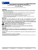
EXTERNAL VIEWS
5
6
7
8
1
2
3
4
1
SW1
2345678
OFF
ON
SW1
1234
OFF
ON
SW2
OFF
ON
SW3
SW2
SW3
Power LED
Status Indicator LED
Configurator Jack
■
SIDE VIEW
■
FRONT VIEW (with the cover open)
DIP switches for configuration
I/O RANGING
The DIP switch setting is required to select I/O types before setting a precise output range using PC Configurator Software
(model: M6CFG).
For detailed information on the PC configuration, refer to the M6CFG users manual.
Table 1. DIP switch setting: Output type
OUTPUT RANGE
SW1-1
SW1-2
SW1-3
SW1-4
SW1-5
SW1-6
SW1-7
SW1-8
0 – 20 mA DC*
1
ON
ON
OFF
OFF
OFF
OFF
ON
OFF
-5 – +5 V DC
OFF
OFF
ON
OFF
ON
OFF
OFF
ON
-10 – +10 V DC
OFF
OFF
ON
OFF
OFF
ON
OFF
ON
*1. For 0 – 1 mA range, set switches as in the table below.
SW1-1
SW1-2
SW1-3
SW1-4
SW1-5
SW1-6
SW1-7
SW1-8
0 – 1 mA DC
OFF
OFF
ON
OFF
OFF
OFF
ON
OFF
Table 2. DIP switch setting: Input Type
INPUT
SW2-1
SW2-2
SW2-3
SW2-4
SW3
DC Voltage or Current
ON
ON
OFF
OFF
ON
Thermocouple
OFF
OFF
ON
OFF
ON
RTD
OFF
OFF
OFF
ON
OFF
Potentiometer
OFF
OFF
OFF
OFF
OFF