MAINTENANCE
5.0 MAINTENANCE
For disassembly, remove 8 screws and lift off top cover. Disassembly is required before
working on the power supply. When replacing any component be certain to use an
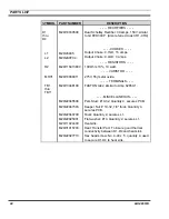
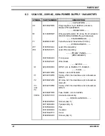
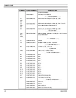
identical component. Thermal joint compound is required between diodes D1, D2, D3,
and D4 and the heat sink.
WARNING
To avoid electrical shock, disconnect power supply from the AC input power source
before removing or replacing any component or assembly.
5.1 TROUBLE-SHOOTING
The troubleshooting procedure in Table 1 may be helpful in isolating a defective
component or assembly in a malfunctioning power supply. When a component or
assembly is identified as defective, replace the defective component with an identical
component. Be sure to check associated circuitry for any other damaged components
before applying power to the unit.
5.2 ADJUSTMENTS
This power supply has no adjustments or controls other than the ON/OFF switch.
5.3 INSTALLATION
The power supply is normally installed in an EIA 19-inch wide rack of a MII/III base
station cabinet. It can also be installed in a 19-inch wide stand alone open rack.
NOTE
Insure that ventilation holes in the unit are not obstructed when the unit is mounted or
in operation.
5.4 FUSE
REPLACEMENT
To replace a defective fuse, perform the following procedure:
1. Place ON/OFF switch to the OFF position.
2. For fuses F1 (F1 & F4 on 19A149979P2), F2, or F3; remove cap from fuse holder
and replace fuse with a fuse of the same type and rating.
WARNING
1. To avoid possible electric shock, DO NOT operate this power supply with the
fuse cover removed.
2. No one should be permitted to handle any portion of the equipment that is
supplied with high voltage, or to connect any external apparatus to the units while
the units are supplied with power. KEEP AWAY FROM LIVE CIRCUITS.
12
LBI-38551D
Содержание P5100 Series
Страница 11: ...CIRCUIT ANALYSIS Figure 4 3 60 Hz Power Supply 19A149979P3 LBI 38551D 11...
Страница 29: ...ASSEMBLY DIAGRAM 289PS15 Sh 2 Rev T LBI 38551D 29...
Страница 30: ...ASSEMBLY DIAGRAM 7 2 12 24 VDC 230VAC 50 Hz POWER SUPPLY 19A149979P2 289PS16 Sh 1 Rev T 30 LBI 38551D...
Страница 31: ...ASSEMBLY DIAGRAM 7 3 12 24 VDC 220VAC 60 Hz POWER SUPPLY 19A149979P3 LBI 38551D 31...
Страница 33: ...OUTLINE DIAGRAM 8 2 PRINTED CIRCUIT BOARD 60 Hz MODELS 19A149979P2 289PS16 LBI 38551D 33...
Страница 34: ...OUTLINE DIAGRAM 8 3 12 24 VDC 220VAC 60 Hz POWER SUPPLY 19A149979P3 289PS25 34 LBI 38551D...
Страница 36: ...SCHEMATIC DIAGRAM 9 2 POWER SUPPLY 19A149979P2 Model 289PS16 289PS16 Rev A 36 LBI 38551 Rev D...
Страница 37: ...SCHEMATIC DIAGRAM 9 3 POWER SUPPLY 19A149979P3 Model 289PS25 Schematic Diagram Not Available LBI 38551 Rev D 37...


