PARTS LIST
SYMBOL
PART NUMBER
DESCRIPTION
W14
From terminal 1 of connector F801A to side
terminal of fuse holder F2.
W15
From terminal 2 of F801A to TB8 on PCB.
W16
Red lead from J801 to side terminal of fuse
holder F3.
W17
Black Lead from J801 to E13 on PCB.
W18
From E8 on PCB to end terminal of fuse holder
F2.
W801 M29/11022301
Power
Cord.
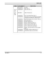
- - - - MISCELLANEOUS - - - -
Item #3
070698702
Case
Item #7
M29/05065600
Bracket for capacitor C9.
Item #9
M29/22043200
Nylon Standoff: Quantity 7; Used to separate
PCB from case.
Item #10
M29/11022000
Strain relief, black similar to Heyco 1200. To
secure W801 to case.
Item #11
11022301
Power Cord.
Item #12
72067900
Terminal boot.
Item #13
31024000
Insulator (Not shown – goes on C1 thru C4 and
C6 and C7.
Item #14
M29/07062201
Top Cover.
Item #15
M29/22041501
Hex nut: No. 6-32 x .250, quantity 10; used to
secure PCB.
Item #16
11024500
Ty-Wraps
Item #17
22046400
Screw: 3.5 mm.
M29/22043800
Machine screw, TORX head: 3.5m x 1/2;
Quantity 8; similar to Camcar/Textron Inc.
Secures cover.
Item #18
M29/22041503
Nut: No. 10-32, quantity 4; used to secure
terminal lugs to PCB.
Item #19
M29/22041502
Hex nut: No. 8-32, quantity 4; secures C9, R1,
and ground wire to case.
Item #20
22008207
Nut: #8-32.
Item #21
M29/22041504
Nut: 1/4-20 x 7/16, quantity 4; secures T1 to
case.
Item #23
M29/22044600
Machine screw, hex head; No. 8-32 x 5/8"
secures C9 to case.
Item #24
40028400
Plug: Housing (Blank).
Item #25
35002900
Pad: 3” x 6” x 3/16”.
Item #26
43019000
High temperature RTV.
LBI-38551D
19
Содержание P5100 Series
Страница 11: ...CIRCUIT ANALYSIS Figure 4 3 60 Hz Power Supply 19A149979P3 LBI 38551D 11...
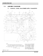
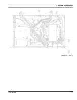
Страница 29: ...ASSEMBLY DIAGRAM 289PS15 Sh 2 Rev T LBI 38551D 29...
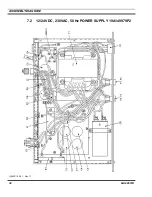
Страница 30: ...ASSEMBLY DIAGRAM 7 2 12 24 VDC 230VAC 50 Hz POWER SUPPLY 19A149979P2 289PS16 Sh 1 Rev T 30 LBI 38551D...
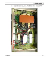
Страница 31: ...ASSEMBLY DIAGRAM 7 3 12 24 VDC 220VAC 60 Hz POWER SUPPLY 19A149979P3 LBI 38551D 31...
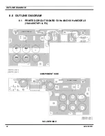
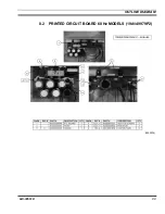
Страница 33: ...OUTLINE DIAGRAM 8 2 PRINTED CIRCUIT BOARD 60 Hz MODELS 19A149979P2 289PS16 LBI 38551D 33...
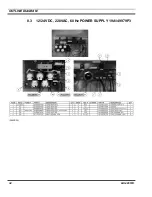
Страница 34: ...OUTLINE DIAGRAM 8 3 12 24 VDC 220VAC 60 Hz POWER SUPPLY 19A149979P3 289PS25 34 LBI 38551D...
Страница 36: ...SCHEMATIC DIAGRAM 9 2 POWER SUPPLY 19A149979P2 Model 289PS16 289PS16 Rev A 36 LBI 38551 Rev D...
Страница 37: ...SCHEMATIC DIAGRAM 9 3 POWER SUPPLY 19A149979P3 Model 289PS25 Schematic Diagram Not Available LBI 38551 Rev D 37...


