LZR FLATSCAN SW Скачать руководство пользователя страница 7

75.5947.04 LZR-FLATSCAN SW 20200612 


Page 7 of 16

75.5947.04 LZR-FLATSCAN SW 20200612 


Page 7 of 16

3

4

ON

1  2   3  4

ON

1  2   3  4

R1

R1

R2

R2

R2

R2

R2

R2

< 1 sec.

1.

4.

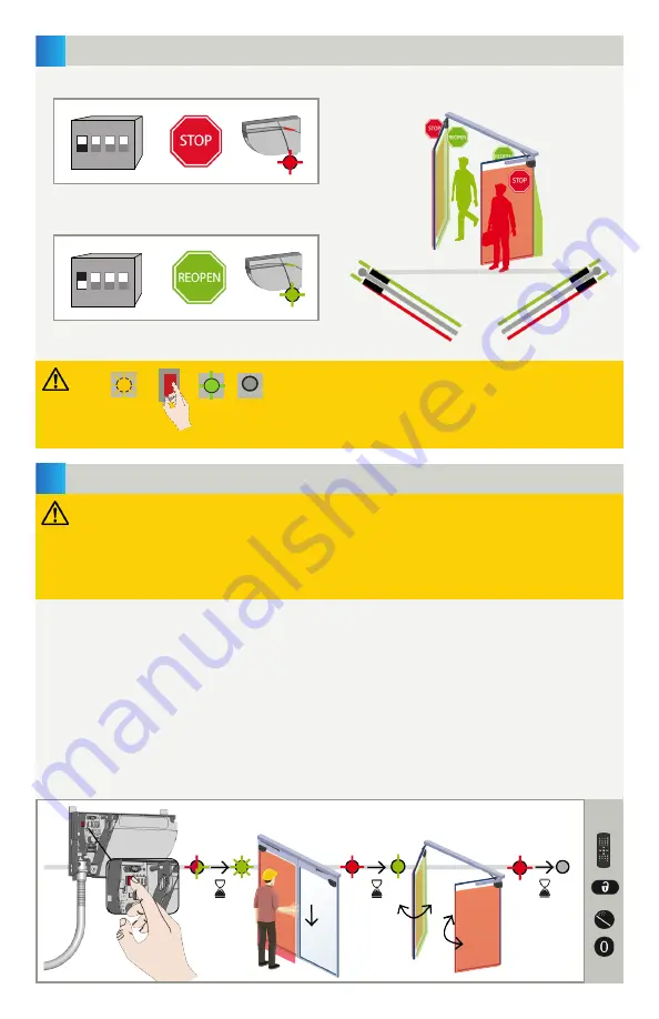
After changing a DIP switch, the orange LED flashes. 

A LONG push on the push button confirms the settings.

Afterwards, a number of green flashes (x) indicates the 

number of connected sensors (x).

RELAY 1: STOP-impulse on swing side of door

RELAY 2: REOPENING-impulse on approach side of door 

X

ORANGE

OFF

GREEN

> 3 sec.

1.  Press the Primary sensor push-button briefly.  The LED will begin quickly flashing red/green. When installing the 

sensor on a pair of doors, repeat this on the second Primary sensor. 

2.  When both sensors flash green, position yourself in front of the door and stretch out your arm in front of you. 

Make an up-and-down motion at the leading-edge to mark the limit of the detection zones. The LED will flash 
red while calculating the width of the door leaves.

3.  When the sensors flash green again, remove yourself from the detection field and cycle the door open to allow 

the sensors to learn the environment.  The sensors will flash red during the closing of the door.

4.  Once the door is completely closed again and the LED is off, the teach-in is complete.

NOTE:


A teach-in on the primary configures both the primary and the secondary. A teach-in on the secondary only 
configures the secondary.  In case the primary and secondary sensor are not aligned, first launch a teach-in on 
the primary and then on the secondary.

Primary

DIP SWITCHES

TEACH-IN

ON (switch 

)

OFF (switch 

)

Before launching a teach-in, ensure the following:

•  door is closed (use Service Mode if needed − see page 8)
•  both relays are connected to door control and primary/secondary cable is connected between sensors
•  detection field is free of environmental obstructions, objects, and people
•  laser window protector is removed

•  verify the relay output setting (see page 10)

2. FIELD WIDTH

3. LEARN

Содержание FLATSCAN SW

Страница 1: ...LATSCAN SW 20200612 Page 1 of 16 75 5947 04 LZR FLATSCAN SW 20200612 Page 1 of 16 LZR FLATSCAN SW EN SAFETY SENSOR FOR FULL AND LOW ENERGY AUTOMATIC SWING DOORS Visit website for available languages o...

Страница 2: ...onnector 6 angle adjustment screw 7 plug 8 clamp 9 cap and screws 10 door loop 11 lock screw 12 laser head 13 laser window 14 laser window protector 15 positioning tabs 16 mounting base 17 primary sec...

Страница 3: ...door control unit and the header cover profile must be correctly grounded Avoid moving objects and light sources in the detection field Do not cover the laser window Avoid vibrations Avoid the presenc...

Страница 4: ...he positioning tabs from the mounting base Fasten the 3 screws using a screwdriver Drill pilot holes 1 8 for sensor mounting For applications requiring a spacer first mount spacer to door and then mou...

Страница 5: ...Remove the sensor cover by inserting your finger and then pull firmly towards you Pass the cable through the hole on the back of the sensor and secure the sensor to the mounting base by sliding it do...

Страница 6: ...r part of the cable to block the wires Secure the door loop to the sensor using the clamp Secure the 2 screws to avoid pulling out the cable Tighten the other side of the door loop using the cable cap...

Страница 7: ...The LED will flash red while calculating the width of the door leaves 3 When the sensors flash green again remove yourself from the detection field and cycle the door open to allow the sensors to lear...

Страница 8: ...be useful during an installation a mechanical learn of the door or maintenance work To enter Service Mode push and hold the button for at least 3 seconds The LED will turn off To exit Service Mode pus...

Страница 9: ...shes x indicates the number of connected sensors x X ORANGE OFF GREEN 3 sec NOTES 1 RELAY 1 RELAY 2 ON OFF DIP 2 ENVIRONMENT standard critical Switch to CRITICAL when external disturbances are likely...

Страница 10: ...obstructions The reaction time increases significantly between value 5 and 9 Measured in inches in specific conditions and dependent on application and installation NO POWER NO DETECTION DETECTION OUT...

Страница 11: ...you do not know the access code cycle the power During 1 minute you can access the sensor without introducing any access code field width 2 35 m To end an adjustment session always lock the sensor Ent...

Страница 12: ...an it carefully with a damp and clean microfibre cloth if necessary attention the surface of the laser window is delicate Switch DIP 2 to off critical environment The sensor does not react at power on...

Страница 13: ...nterface card and laser head The ORANGE LED flashes 4 x every 3 seconds The sensor does not see its background Using the remote control set the background to 0 off deactivates background Something clo...

Страница 14: ...15 Power consumption 2 W Response time Door leaf safety max 50 ms Pinch zone safety max 90 ms Test input 30 VDC max switching voltage low 1 V high 10 V voltage threshold Output max switching voltage m...

Страница 15: ...13 21 13 65 14 09 14 53 7 7 07 7 16 7 28 7 43 7 62 7 83 8 06 8 32 8 60 8 90 9 22 9 55 9 90 10 26 10 63 11 01 11 40 11 80 12 21 12 62 13 04 13 46 13 89 14 33 14 76 7 5 7 57 7 65 7 76 7 91 8 08 8 28 8...

Страница 16: ...med ensuring that the sensor system installation is compliant with local national and international regulations codes and standards Once installation or service work is complete a safety inspection of...

Отзывы: