


© 2016 Lytx, Inc. – Confidential & Proprietary
19
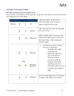
Use a voltmeter to make sure the circuit provides continuous 12V or 24V power when the
key is removed from the ignition and all lights, devices and switches are off.
Current Draw
Tapping into an existing vehicle wire, make sure it can handle the additional current draw of
the event recorder.
A wire that reads 12V on a voltmeter may not necessarily be able to supply enough current
to the existing circuit and the event recorder.
Gauge of wire being tapped into provides a good indication. A larger gauge wire is often the
best choice, but make sure to test it with a load.
Connecting the
BROWN
WIRE to a 12V-24V power source that is IGNITION-SWITCHED
Used to sense when the ignition is switched on.
Requires a power source that is “on” only when the key is turned all the way forward to the
“on” position and when the engine is running.
CAUTION – Test the connection before completing any further installation procedures.
Common Mistake
This connection is often (mistakenly) made to a modulated circuit – one that comes out of a
computer control module running some subsystem in the vehicle – which can give false ignition
on/off signals. To avoid this, make sure to connect this wire to a circuit that is on the battery side
of any modules. Consult the vehicle wiring schematics or a local authorized dealership to obtain
this information.
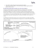
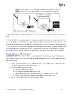
Route the DC3P Cable
You may need to remove the window and door trim to route the cable underneath. These typically
snap on and off using special clips. In vehicles with side and curtain airbags, the clips are often
IMPORTANT: Needs to be connected properly
or can give false ignition signals.
CAUTION: An improper connection could impact the
program and functionality (i.e.-fleet tracking, hibernation, etc.)