Reference Manual C DA 5010 Version1.8
Page 15
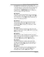
changed from the remote control system. This
overrides the local dip switches regardless of Switch
1 ON/OFF setting. To ensure the module reads the
local dip switch settings it is recommended to
toggle Switch 1
ON-OFF-ON
before making any
local changes to the dip switches
.
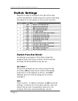
Dip Switch 2
This switch selects either RGB or YUV component
analog outputs from the module.
ON
= RGB,
OFF
=
YUV Only active when
Note:
Outputs selected on
Switch 3 are always present.
Dip Switch 3
This is used to select the second set of analog
outputs from the module.
ON
will set 3 x CVBS
outputs and
OFF
will select1X CVBS and S Video
(Y/C) outputs.
Dip Switch 4
This switch will select the internal color bars, and
these will pear on all outputs.
ON
selects color bars
OFF
turns them off.
Dip Switch 5
This selects the video standard for the color bar
signal. This does not automatically change with the
input auto detection, and has to selected
manually.
ON
selected NTSC,
OFF
selects PAL
Dip Switch 6
Switch 6 and Switch 7 select what output the
module should provide when the input signal is
removed or missing.
ON
makes Switch 7 active.
OFF
selects color bars.
Dip Switch 7
If Switch 6 is ON the output is disabled when the
input signal is removed or missing.
ON
selects
disabled output output.
OFF
selects black.


