16
USE
• This unit can be used to process wood stocks which are within
800 mm in lenght and 152 mm in width.
• This unit can not be used to process metal materials and other
non-metal materials but wood mateirals.
ASSEMBLY INSTRICTUON
Due to packaging requirements, your belt sander is partly
assembled. Please do not operate this belt sander before it is com-
pletely assembled and all bolts are completely secured. The num-
ber shown in bracket is the part number. Please refer to the assem-
bly diagram A (or B if needed) to assembly the belt sander. The fol-
lowing are the steps to complete the assembly of the belt sander.
Step 1:
Assemble the stand. Please note that the short bars (# 95)
are always ride on the long bars (#96) and the bolt holes are always
aligned.
Step 2:
Put the main assembly on the stand and fix it on the stand
with 4 bolts (#92) and 4 screws (#93).
Step 3:
Attach the long (front) table to the main assembly. Inser
the U-bar (#85) into the two slot on the supporting frame of the
table. Then insert the U-bar with the table into the slots on the main
assembly. Both end of the U-bar must be penetrated through the
two hols behind the main assembly. Inser a pin (#84) into the pin
hole at each end of the U-bar.
Step 4:
Attach the short (side) table to the main assembly with the
four bolts (#47) and four screws (#62). Then attach the pointer
(#66). The degree label is properly turned in factory, when the
table is at its level position, the pointer must be pointing at 90
degree. If not, please loose the four bolts (#47) and adjust it.
CHANING SANDING BELT
To change sanding belt, open the cover (#58), then pull off the bar
(#35), loosen the bolt (#45) that on the dust hood (#44). Turn the
tension handle to left (anticlockwise). Take out the sanding belt
and replace with a new one. Recover all steps previously done.
Because the size of a new sanding belt is slightly different from the
old one, it may affect the alignment. Proper tracking is achieved
when drive roller and idler roller are aligned to fit the sander belt.
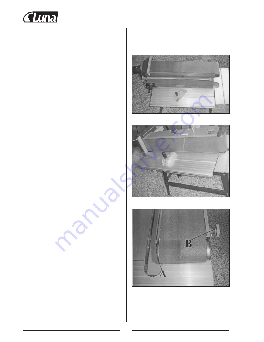
The knob (#14) is used to tilt the idler roller. (3). The main opera-
tion method goes as follows.
Fig. 1. Adjust the sanding belt to horizontal position.
Fig. 3. Adjust the screw A and knob B to have the sanding machi-
ne run between the rollers.
ENGLISH
CONTENTS
Use ...............................................................................................16
Assembly instruction ...................................................................16
Warning ........................................................................................17
Specification.................................................................................18
Grounding instructions.................................................................18
Electrical diagram ........................................................................18
Wiring diagram ............................................................................18
Exhausting system .......................................................................18
The power supply.........................................................................18
Unloading from a vehicle and installation...................................19
Cleaning and oiling ......................................................................19
Repairs .........................................................................................19
Exploded view + partslist ............................................................40
EC Declaration of conformity .....................................................42
CAUTION:
Read the instruction manual before using the
appliance
Fig. 2. Adjust the sanding belt to vertical position.
Original instructions
Содержание BBS 2000
Страница 1: ...Bandputs Belt sanding machine BBS 2000 20558 0103 20558 0202 20558 5003 BBS 2000...
Страница 41: ...40...
Страница 46: ......
Страница 47: ......


