background image

3C

6

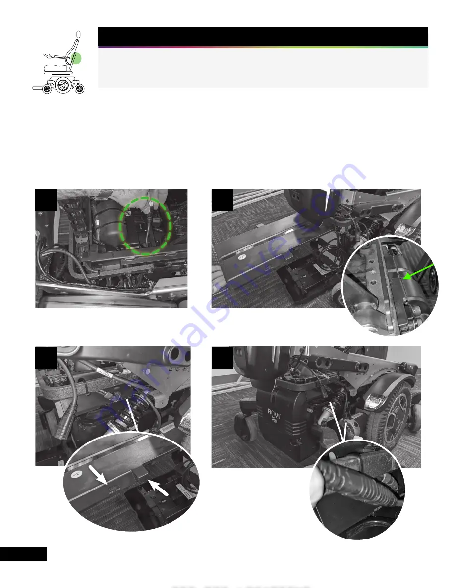
STEP 3 - CONNECT LUCI

Route the male RNET cable from LUCI through the side of the wheelchair (Figure 3A) and plug it 
into the wheelchair power module. Reinstall the base cover, ensuring that the cover lines up prop-
erly at the front of the wheelchair (Figure 3B). The RNET cables should exit the cover through the 
forwardmost opening and the spiral cable should exit through the rearmost opening (Figure 3C). 
Reinstall the rear cover using the original thumbscrews (Figure 3D). Plug the male RNET cable 
from the wheelchair into the female RNET cable on the LUCI SmartFrame.

No Tools Required

3A

3B

RNET CABLE 

EXIT

ZIP TIE LOCATIONS

3D

FRONT OF 

WHEELCHAIR

SPIRAL CABLE 

EXIT

Содержание SmartFrame ROVI X3

Страница 1: ...INSTALLATION GUIDE ROVI X3...

Страница 2: ...H Color Joystick Spacer 1 I CJSM 1 2 Dashboard Bracket 1 J OMNI Dashboard Bracket 1 K Alcohol Wipe 2 L LuciLink Hub Wheelchair Key 1 M 3 16 Drill Bit 1 N M5 x 10mm Flange Screw 6 O M5 x 8mm Hex Head...

Страница 3: ...ly endorsement For more information visit luci com patents ROVI X3 INDIVIDUAL FOOTPLATES DRILL GUIDE Tear this template along the perforated lines for the correct size footplate Line up the green edge...

Страница 4: ...the farthest setting Use a flathead screw driver to pull the plastic rivets out and remove the rear cover Figure 1B Place the LUCI SmartFrame A on the floor behind the wheelchair Figure 1C Remove the...

Страница 5: ...into the LUCI Subframe on each side of the wheelchair Figure 2B Slide the LUCI SmartFrame A onto the wheelchair lining up the front mounting holes Figure 2C Clip the frame onto the standoff Figure 2D...

Страница 6: ...the front of the wheelchair Figure 3B The RNET cables should exit the cover through the forwardmost opening and the spiral cable should exit through the rearmost opening Figure 3C Reinstall the rear c...

Страница 7: ...riented as shown and the cable opening is at the bottom Figure 4B Route the USB cable from the LUCI SmartFrame toward the drag chain leaving a few inches of slack at the bottom so that the cable is no...

Страница 8: ...slide into the slots in the Luci Subframe Figure 5B Insert two M5 x 10mm flange screws N in each side of the LUCI SmartFrame and tighten with a 3mm Allen wrench Figure 5C Note It may be necessary to p...

Страница 9: ...for single footplate and tape it in place Figure 6A Drill the three holes with the 3 16 Drill Bit M Replace the rubber and drill holes through it from the bottom of the footplate Set the Scout on top...

Страница 10: ...ean the plastic before applying the adhesive cable clip The cable clip needs firm pressure to properly adhere and may come off in the first few minutes if moved too aggressively when putting the cable...

Страница 11: ...7C 7D 7E 7F ZIP TIE LOCATIONS CABLE CLIP 7G INSERT CABLE INTO CABLE CLAMP EXACTLY AS SHOWN 7A 7B ZIP TIE 11...

Страница 12: ...red the Scout should be adjusted to an orientation that is level with the ground to ensure proper functioning and obstacle detection The adjustable footplate bracket allows for variability in Scout or...

Страница 13: ...to attach the LED Joystick Dashboard Bracket F to the back of the Dashboard D with the Dashboard Reference Card E behind the bracket Figure 8A3 Route the Dashboard cable along the lower inside bend of...

Страница 14: ...ket G Figure 8B3 Choose the correct left or right Dashboard Reference Card E Use four 4 40 x 3 16 inch screws P to attach the Color Joystick Dashboard Bracket G to the back of the Dashboard D with the...

Страница 15: ...ference Card E Use four 4 40 x 3 16 inch screws P to attach the CJSM 1 2 Joystick Dashboard Bracket I to the back of the Dashboard D sandwiching the Dashboard Reference Card E between them and ensurin...

Страница 16: ...d bracket J between the armrest and the Omni module and attach using two M5 x 8mm hex head screws O Figure 8D2 Route the Dashboard cable toward the back of the wheelchair following existing cabling an...

Страница 17: ...ert and tighten the three screws Ensure all cables are properly routed and zip tie as necessary Trim zip tie tails Note It may be easier to place the cables and close the LuciLink Hub by removing the...

Страница 18: ...ng any cables or compressing any parts of LUCI Ensure that leg pads and accessories such as lateral thigh supports do not contact or block the front camera pods at the lowest seat elevation Confirm th...

Страница 19: ...rt one screw on each side into the sub frame Rest the LUCI SmartFrame on the two screws 3 Swap the batteries as you normally would It may be necessary to move the excess USB cables out of the way whil...

Страница 20: ...LUCI COM P002 054 v 2 0...

Отзывы: