background image

Configuring the OC12-ATM Trunk Module

OC12-ATM trunk module specifications

Stinger OC12-ATM Trunk Module Guide 

 3

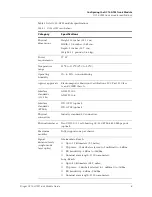
Table 1 lists OC12-ATM module specifications.

Table 1.  OC12-ATM specifications  

Category

Specifications

Physical 
dimensions

Height: 15 inches (38.1 cm).

Width: 1.06 inches (2.69 cm).

Depth: 5 inches (12.7 cm). 

Weight: 1.5 pounds (0.68 kg).

Power 
requirements

17 W

Temperature 
range 

32

°

F to 131

°

F (0

°

 C to 55

°

C).

Operating 
humidity

0% to 90%, noncondensing.

Agency approvals

Electromagnetic Emissions Certifications: FCC Part 15 Class 
A, and CISPR Class A. 

Interface 
standards 
(OC-12c)

ANSI T1.105.

ANSI T1.106.

Interface 
standards 
(STM-4)

ITU G.957 (optical).

ITU G.709 (optical).

Physical 
connectors

Industry standard LC connectors. 

Physical interfaces 

Two UNI 3.0/3.1 cell-bearing OC-12c/STM-4 622-Mbps ports 
(optical). 

Maximum 
modules

Fully supports one per chassis.

Signal 
distance/levels 
(single-mode 
laser optics)

Intermediate-Reach:

Up to 15 kilometers (9.3 miles).

TX power: -15 decibels referred to 1 milliwatt to -8dBm.

RX Sensitivity: -8dBm to -28dBm.

Nominal wavelength: 1310 nanometers.

Long-Reach:

Up to 40 kilometers (24.9 miles).

TX power: -2 decibels referred to 1 milliwatt to -3dBm.

RX Sensitivity: -8dBm, -28dBm.

Nominal wavelength: 1310 nanometers.

Содержание Stinger OC12-ATM

Страница 1: ...Stinger OC12 ATM Trunk Module Guide For software version 9 5 206 August 2003 ...

Страница 2: ...l Declaration of Conformity certificate for this equipment according to EN 45014 access the Lucent INS online documentation library at http www lucentdocs com ins Safety compliance and warranty Information Before handling any Lucent Access Networks hardware product read the Edge Access and Broadband Access Safety and Compliance Guide included in your product package See that guide also to determin...

Страница 3: ...mber Software version or release number Software and hardware options If supplied by your carrier service profile identifiers SPIDs associated with your line Your local telephone company s switch type and operating mode such as AT T 5ESS Custom or Northern Telecom National ISDN 1 Whether you are routing or bridging with your Lucent product Type of computer you are using Description of the problem ...

Страница 4: ......

Страница 5: ...ups 10 Changing physical layer interface settings 11 Configuring call control 11 Example of OC12 ATM configuration 12 Checking OC12 ATM trunk interface status 13 Monitoring errors and performance of the SONET payload 19 Checking daughter card status 22 Automatic protection switching APS 24 Overview of APS operation 24 Profiles associated with APS 25 Configuring APS 25 The sonet profile 25 The APS ...

Страница 6: ......

Страница 7: ...Stinger OC12 ATM Trunk Module Guide vii Figures Figure 1 OC12 ATM trunk module 5 Figure 2 OC12 interfaces to the ATM network 13 Figure 3 SONET layers 19 ...

Страница 8: ......

Страница 9: ...Stinger OC12 ATM Trunk Module Guide ix Tables Table 1 OC12 ATM specifications 3 Table 2 OC12 trunk module status lights 5 ...

Страница 10: ......

Страница 11: ...nd line interface CLI You should understand the fundamental concepts of digital subscriber line DSL technology and be familiar with the relationship between DSL interfaces and associated configuration profiles Documentation conventions Following are all the special characters and typographical conventions used in this manual Convention Meaning Monospace text Represents text that appears on your co...

Страница 12: ...ackets indicate an optional argument you might add to a command To include such an argument type only the information inside the brackets Do not type the brackets unless they appear in boldface Separates command choices that are mutually exclusive Points to the next level in the path to a parameter or menu item The item that follows the angle bracket is one of the options that appear when you sele...

Страница 13: ... include IP routed switch through ATM PVCs and RFC 1483 PVCs that terminate on the IP2000 IEEE 802 1Q VLAN and forwarding multicast video transmissions on DSL interfaces Stinger Private Network to Network Interface PNNI Supplement Provides quick start instructions for configuring PNNI and soft PVCs SPVCs and describes the related profiles and commands in the Stinger command line interface Stinger ...

Страница 14: ......

Страница 15: ...igured as one active port and one standby port to provide a 1 1 APS connection to the ATM switch A Stinger FS or FS chassis fully supports a maximum of one OC12 trunk module per chassis This OC12 trunk module can be used in combination with an OC3 DS3 or E3 trunk module in the other trunk module slot and with TRAM cards in the unit Two versions of the OC12 ATM trunk module are supported OC12 ATM s...

Страница 16: ...C12 ATM trunk module and connecting it to a link to an ATM switch you verify connection by checking the status lights You then configure the physical link Use a status profile to display the state of the OC12 line and any error conditions OC12 ATM trunk module specifications The OC12 ATM trunk module provides two 622 Mbps ports for optical connections Each port supports the STS 12c and the STM 4 i...

Страница 17: ...FCC Part 15 Class A and CISPR Class A Interface standards OC 12c ANSI T1 105 ANSI T1 106 Interface standards STM 4 ITU G 957 optical ITU G 709 optical Physical connectors Industry standard LC connectors Physicalinterfaces Two UNI 3 0 3 1 cell bearing OC 12c STM 4 622 Mbps ports optical Maximum modules Fully supports one per chassis Signal distance levels single mode laser optics Intermediate Reach...

Страница 18: ... that appear directly above each port connector Figure 1 shows the OC12 ATM trunk module Minimum bend radius 3 inches 7 62 cm Other OC 12 standards ATM Forum UNI 3 0 3 1 ANSI T1M1 3 92 005R1 Bellcore TR NWT 001112 Bellcore GR 253 CORE RFC 1595 Other STM standards ATM Forum UNI 3 0 3 1 ANSI T1M1 3 92 005R1 Bellcore GR 253 CORE RFC 1595 Table 1 OC12 ATM specifications Continued Category Specificatio...

Страница 19: ...e 2 OC12 trunk module status lights Status light Color Condition Indicates APS Amber On The associated port is the current active channel in a protection group ALARM Amber On The associated port is configured and is in an alarm condition PORT Green On The associated OC12 port is enabled and not in an alarm condition STGR STGR OC 12 OC 12 POR PORT 1 T 1 POR PORT 2 T 2 APX APX ALARM ALARM POR PORT A...

Страница 20: ... a trunk module in slot 17 in SONET shelf 1 trunk module 1 1 name 1 17 1 physical address shelf 1 trunk module 1 1 enabled no ignore lineup system defined aps config name line config 0 851 payload atm no loopback sonet no no vpi 0 255 vci 32 8191 atm config ast x43 ast x43 yes spare physical address any shelf any slot 0 sparing mode inactive Parameter Specifies name Identifies the name of the inte...

Страница 21: ...ters details below spare physical address Not used sparing mode Not used Parameter Specifies trunk group Not currently used Leave the default value zero nailed group Sets the nailed group number for the OC12 ATM physical interface A connection or radius profile specifies this number to use the interface Each interface is assigned a unique default number so you do not need to modify this parameter ...

Страница 22: ...loopback Specifies an ATM layer loopback Data is looped back to the local end from the line side of the ATM framer framing mode Sets the type of framing used on the line Valid values are sonet default for use with OC12 lines sdh for use with STM 4 lines rx descramble disabled Enables or disables descrambling of the receive stream Valid values are no default descrambling is not disabled yes descram...

Страница 23: ...ort This requires reservation of more VCCs on all VPIs that are configured for VC switching Caution Changes to this parameter take effect as soon as the profile is saved requiring reset and re connection of all connections in the system This will result in a loss of data clock source Designates if the interface will be considered as a clock source depending on its priority Valid values are eligibl...

Страница 24: ...TM trunks E3 Lines dvOp dvUpSt dvRq sAdm nailg All OC12 lines dvOp dvUpSt dvRq sAdm nailg Line 1 17 1 Up Assign UP UP 00801 Line 1 17 2 Up Assign UP UP 00802 Parameter Specifies rx scrambler type Selects the type of algorithm used to descramble the signal being received Valid entries are ast none The received signal has not been scrambled ast x31 The received signal has been scrambled using the po...

Страница 25: ...nd HDSL2 LIMs The call control mechanism enables the Stinger unit to establish and maintain soft PVCs SPVCs across port state changes This allows xDSL subscribers to establish connections on LIM interfaces in the operating states before they are fully trained as well as in the standard port up state in which the modem has successfully trained up SPVC connections are accepted when the modem has not...

Страница 26: ...etermining whether calls are established or not Specify one of the following values no the default The Stinger call control mechanism allows calls to be established when the line state is up and disallow calls when the line state is down yes The Stinger call control mechanism ignores the line state and allows calls to be established on a port as long as the specified slot is operational and the sp...

Страница 27: ...12 interfaces The profiles provide information about the state of the physical interfaces error counters and ATM framer status information The performance monitoring and interval performance monitoring subprofiles provide counters for the SONET payload The following display shows sonet stat parameters for the physical interface with sample settings for an active line in SONET STAT shelf 1 trunk mo...

Страница 28: ...cp chcs error count 0 racp uchcs error count 0 racp rx cell count 0 tacp tx cell count 0 frequency justification count 0 HEC cell drop counter 0 FIFO overflow counter 0 idle cell counter 0 valid cell counter 0 short packet counter 0 bad crc packet counter 0 bad seq packet counter 0 valid packet counter 0 time elapsed 743 valid intervals 79 performance monitoring 646 664 0 46350 0 0 0 664 0 0 0 0 0...

Страница 29: ...vpi vci Range Current valid VCI range configured for the port It can reflect one of the following vpi 0 255 vci 32 255 vpi 0 255 vci 32 511 vpi 0 255 vci 32 1023 vpi 0 255 vci 32 2047 vpi 0 255 vci 32 4095 vpi 0 255 vci 32 8191 vpi 0 255 vci 32 16383 vc switching vpi Array of VPIs used for virtual circuit switching VCC Other VIPs are used for virtual path VP switching vcc vpi For internal use only...

Страница 30: ...signal degrade sd conditions when the line bit error rate exceeds the configured threshold as reported from the far end by the K1 K2 bytes of the SONET frame aps channel recv sf count Indicates the number of signal failure sf conditions This can be a loss of signal loss of frame or AIS L or BER exceeding the configured threshold aps channel recv ais count Indicates the number of line alarm indicat...

Страница 31: ...te devect indicator signal is indicating a problem at the distant end sonet path unequipped The SONET path is in an unequipped state sonet path signal label mismatch The SONET path is experiencing a signal label mismatch sonet path ber sf error The SONET path is in a bit error signal failure state ais receive Far end is sending an alarm indication signal AIS False indicates that the local device h...

Страница 32: ...ceive cell count tacp tx cell count Transmit ATM Cell Processor TACP transmit cell count frequency justification count Number of frequency justification operations hec cell drop counter Number of cells dropped by HEC processing fifo overflow counter Number of cells dropped because of first in first out FIFO overflow idle cell counter Total number of idle cells received valid cell counter Total num...

Страница 33: ...ounters are maintained at the section line path SONET layers see Figure 3 Figure 3 SONET layers As shown in Figure 3 a SONET section is a single run of cable Section terminating equipment is any adjacent pair of switches A line is one or more sections A path is an end to end circuit Coding violations are bit interleaved parity errors detected in the incoming signal A severely errored frame defect ...

Страница 34: ...net line coding violations 0 sonet line unavailable seconds 664 sonet far end line errored seconds 0 sonet far end line severely errored seconds 0 sonet far end line coding violations 0 sonet far end line unavailable seconds 0 sonet path errored seconds 0 sonet path severely errored seconds 0 sonet path coding violations 0 sonet path unavailable seconds 0 sonet far end path errored seconds 0 sonet...

Страница 35: ...ns The number of coding violations encountered at the far end of a SONET line Not collected at this time This parameter will always display 0 sonet far end line unavailable seconds The number of seconds a SONET line was unavailable at the far end Not collected at this time This parameter will always display 0 sonet path errored seconds The number of errored seconds encountered by a SONET path sone...

Страница 36: ...shows the trunk daughter dev parameters for the daughter card of an OC12 ATM module in TRUNK DAUGHTER DEV shelf 1 trunk module 1 1 device address shelf 1 trunk module 1 1 device state trunk daughter oper state up trunk daughter type trunk daughter oc12 previous trunk daughter type trunk daughter none transceiver info reach none interface oc12 Parameter Indicates device address Physical location of...

Страница 37: ...ima 8t1 trunk daughter ima 8e1 trunk daughter 16oc3 trunk daughter oc12 previous trunk daughter type The previous type of trunk daughter card in this slot One of the following will be displayed depending on the type of trunk card previously installed trunk daughter none trunk daughter ds3 trunk daughter oc3 ds3 combo trunk daughter 0c3 single trunk daughter ds3 single trunk daughter e3 trunk daugh...

Страница 38: ...that the backup or protection channel begin carrying data in less than 50 milliseconds This transfer on the OC12 ATM trunk module typically occurs in approximately 20 milliseconds Data loss is minimal and VPI VCI connections do not need to be reestablished APS also allows redundant lines between Stinger units and any other device that supports linear 1 1 APS compliant with SR NWT 001756 6 and GR 2...

Страница 39: ...le is activated the trunk channel joins the protection group as defined in the aps config profile The following lists the sonet profile for an OC12 ATM trunk module in slot 17 with the aps config name of pg1 admin dir sonet 132 06 09 2003 15 46 15 shelf 1 trunk module 1 1 1 17 1 129 06 09 2003 15 46 15 shelf 1 trunk module 1 2 1 17 2 admin read sonet 1 17 1 SONET shelf 1 trunk module 1 1 read admi...

Страница 40: ... characteristics and nailed group When a protection group is deactivated the trunk profile sonet of the protection port is restored to factory values Following is a sample profile with default values admin new APS CONFIG APS CONFIG read admin list in APS CONFIG new name active no linear protection channel any shelf any slot 0 protection mode 1 1 direction mode unidirectional revertive mode non rev...

Страница 41: ...king channel has recovered from a failure Valid range is from 0 through 4 294 967 295 The default is 3000 psbf failure timer duration Protection switching byte failure PSBF failure timer duration in tens of milliseconds The amount of elapsed time before a failure is detected when the local end persistently receives an invalid or unacceptable code in the K1 byte The valid range is from 0 through 4 ...

Страница 42: ... channel indications must match before the channel mismatch failure is cleared Valid range is from 0 through 4 294 967 295 The default is 1000 fepl mismatch failure timer duration Timer duration of the far end protection line FEPL failure in tens of milliseconds This timer sets the amount of time before a far end protection line failure is detected when the local end receives an SF signal failure ...

Страница 43: ...M trunk module in slot 17 and set aps config name in the sonet profile to pg1 the name of the aps config profile describing the protection channel This is shown in the example below admin read sonet 1 17 1 SONET 1 17 1 admin set enabled yes admin set aps config name pg1 admin write When this profile is written APS is activated and the protection channel on port 1 17 2 is automatically enabled Caut...

Страница 44: ... Current status of the channel port Valid values are on protection The channel is currently switched to the protection channel on working The channel is currently switched to the working channel aps channel sd condition Whether there is currently a signal degrade condition line bit error rate beyond the configured threshold Valid values are true and false aps channel sf condition Whether there is ...

Страница 45: ...t 0 recv mode mismatch count 0 recv channel mismatch count 0 recv fepl count 0 extra traffic flag False protection mode 1 1 direction mode bidirectional revertive mode revertive rx k1 byte value 00 rx k2 byte value 05 aps channel sd count Number of signal degrade conditions line bit error rates beyond the configured threshold received over the K1K2 APS channel from the far end Valid range is from ...

Страница 46: ...version 1 1 otherwise false is displayed last switch time Time stamp in milliseconds since last time a protection switch occurred Valid range is from 0 through 2147483647 switch count Number of times switch over to protection channel has occurred aps cfg creation time Time the protection group was created number of channels Number of channels in this protection group Valid range is from 0 through ...

Страница 47: ...2147483647 extra traffic flag Not currently used reserved for later versions of APS Whether extra traffic is being carried on the protection channel True if extra traffic is being carried protection mode The linear APS protection mode 1 1 1 n Currently only 1 1 is supported direction mode Whether the protection group s direction mode is unidirectional or bidirectional revertive mode Whether the pr...

Страница 48: ...hes traffic currently on working channel to protection channel fsp Force Switch of Protection to working Switches the switched traffic from the protection channel back to the working channel msw Manual Switch of Working to protection A low priority version of FSW msp Manual Switch of Protection to working A low priority version of FSP exer EXERcise Tests the signaling protocol clear Clears managem...

Страница 49: ...ion Name Specifies the name of the protection group and of the aps config profile PG Specifies the number of the protection group Work Specifies the address of the working channel Prot Specifies the address of the protection backup channel RevMode Specifies whether channel operation is revertive Rever or nonrevertive Non rev DirMode Specifies whether channel directional mode is unidirectional Uni ...

Страница 50: ......

Отзывы: