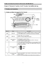
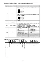
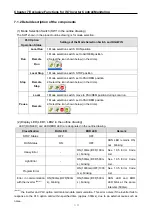
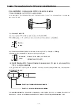


Chapter 7 Exclusive Functions for iS7 Inverter Control/Monitoring
7-15
7.2.3 Monitoring (PLC Option
Í
Inverter)
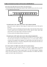
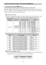
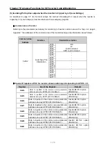
(1) Using inverter digital input points as the digital input points of PLC option
Maximum 11 digital input points of inverter (with basic 10 points mounted: 8 points, with 10 extension points:
basic 10 + 3 points) can be used as the digital input points of PLC option. Or, the status (0 or 1) of inverter
digital input points can be used simply for monitoring function.
▶
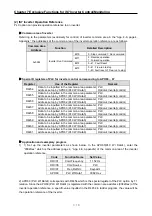
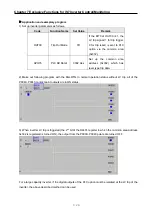
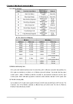
Common area of inverter
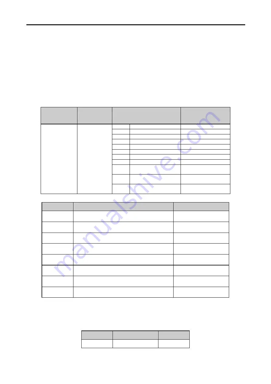
Referring to the parameters (exclusively for monitoring) of inverter common area in the “App. 4-2, page 4,
Appendix,” the addresses of the common area of the inverter digital input status are as follows.
Common Area
Address
Function
Detailed Description
Remark
BIT0
0: P1 OFF 1: P1 ON
Built-in (IN65)
BIT1
0: P2 OFF 1: P2 ON
Built-in (IN66)
BIT2
0: P3 OFF 1: P3 ON
Built-in (IN67)
BIT3
0: P4 OFF 1: P4 ON
Built-in (IN68)
BIT4
0: P5 OFF 1: P5 ON
Built-in (IN69)
BIT5
0: P6 OFF 1: P6 ON
Built-in (IN70)
BIT6
0: P7 OFF 1: P7 ON
Built-in (IN71)
BIT7
0: P8 OFF 1: P8 ON
Built-in (IN72)
BIT8
0: P9 OFF 1: P9 ON
In case expansion I/O is
installed (IN73)
BIT9
0: P10 OFF 1: P10 ON
In case expansion I/O is
installed (IN74)
0320 Hex
Information of
Inverter Digital
Input Point
BIT10
0: P11 OFF 1: P11 ON
In case expansion I/O is
installed (IN75)
▶
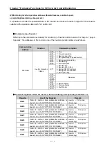
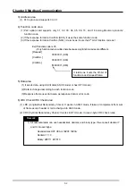
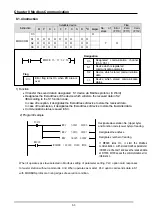
Special D registers of PLC for inverter status monitoring corresponding to APO76 ~ 83
Register
Use of the Register
Remark
D4474
Data of common area parameter address is
saved set up by APO76 (PLC Rd Data1).
Inverter
→
PLC option
(Monitoring)
D4475
Data of common area parameter address is
saved set up by APO77 (PLC Rd Data2).
Inverter
→
PLC option
(Monitoring)
D4476
Data of common area parameter address is
saved set up by APO78 (PLC Rd Data3).
Inverter
→
PLC option
(Monitoring)
D4477
Data of common area parameter address is
saved set up by APO79 (PLC Rd Data4).
Inverter
→
PLC option
(Monitoring)
D4478
Data of common area parameter address is
saved set up by APO80 (PLC Rd Data5).
Inverter
→
PLC option
(Monitoring)
D4479
Data of common area parameter address is
saved set up by APO81 (PLC Rd Data6).
Inverter
→
PLC option
(Monitoring)
D4480
Data of common area parameter address is
saved set up by APO82 (PLC Rd Data7).
Inverter
→
PLC option
(Monitoring)
D4481
Data of common area parameter address is
saved set up by APO83 (PLC Rd Data8).
Inverter
→
PLC option
(Monitoring)
▶
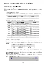
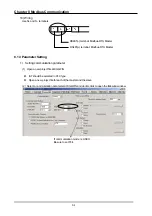
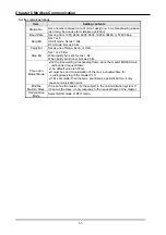
Application and exemplary program
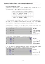
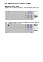
1) Set up inverter parameters as follows. Especially, enter 320Hex which is the inverter digital input
status address (App. 4-2. page 4, Appendix) in the APO76 (PLC Rd Data1).
Code
Function Name
Set Value
APO76
PLC Rd Data1
0320 Hex
Содержание SV-iS7 PLC
Страница 46: ...Chapter 5 Input and Output Function 5 5 Load ...


