


I185 GB 06 15
LRX D01
113
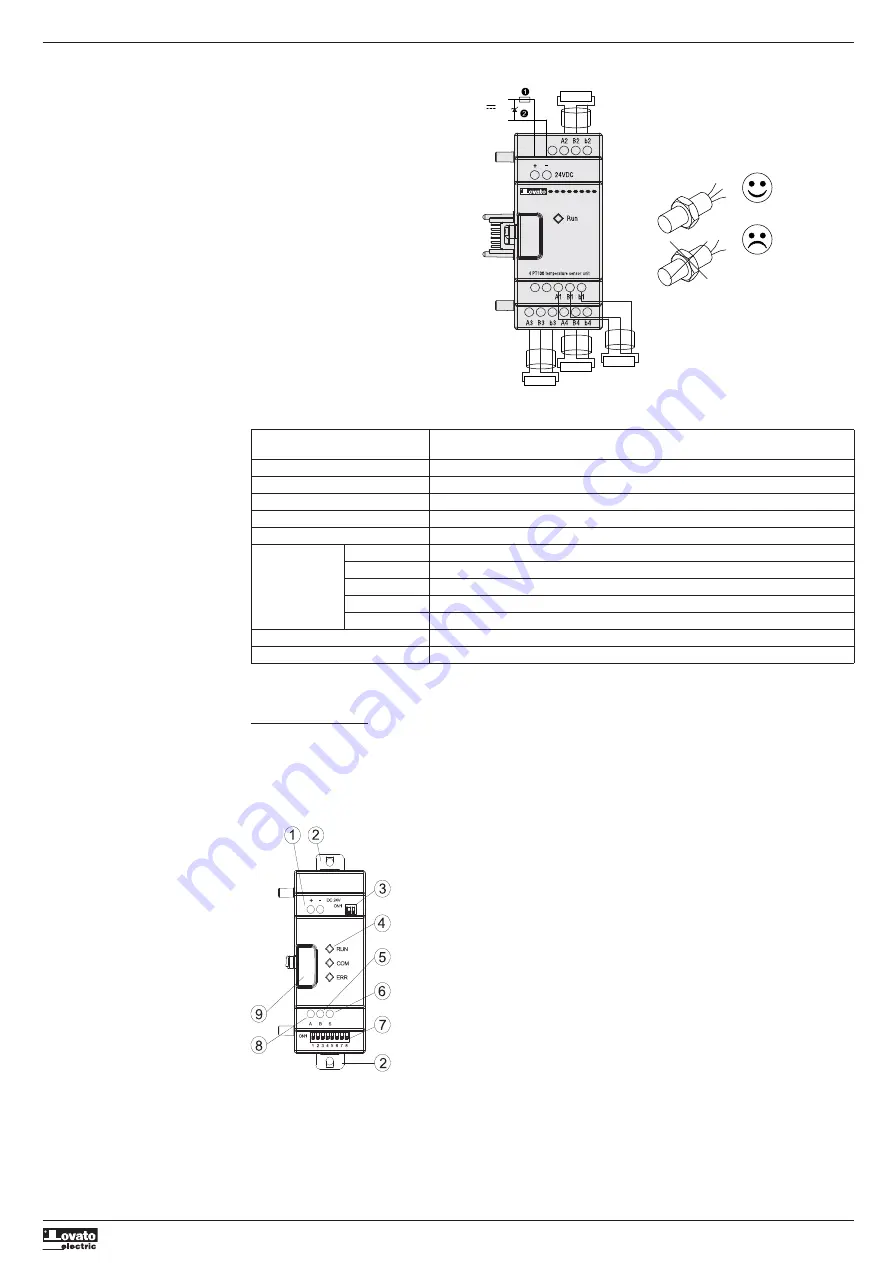
Wiring of LRE04PD024 module
When the temperature is out of the -100°C…+600°C range limits, error output coils M34, M35, M36 and M37, which correspond to channel 1,
channel 2, channel 3 and channel 4, will be activated (ON).
PT100
-
24VDC
+
External
equipment
PT100
PT100
PT100
Characteristics
Specifications
(Analog input unit,4 PT100 temperature sensor input channel)
Input temperature range
-100°C…+600°C
Digital output
-100.0°C…+600.0°C
Resolution
0.1°C
Accuracy
±1%
Total number of channels
4
A1~A4
Terminal A - Heat sensor (PT100) signal input
B1~B4
Terminal B - Heat sensor (PT100) signal input
Terminal block
b1~b4
Terminal b - Heat sensor (PT100) signal input
+
+24V DC power supply input (+)
–
+24V DC power supply input (-)
Auxiliary power supply
24VDC
Ambient operating temperature
-20°C…+55°C
- Power supply
- 35mm DIN rail clip or screw fixing using M4x15mm type.
- 2-bit switch SW2 (terminal resistance selection with both at ON)
- LREP00 status indication LED - RUN
- RS485 serial port – B terminal
- RS485 serial port - Screen
- 8-bit switch SW1-1 to SW1-8 for LREP00 configuration
- RS485 serial port – A terminal
- Expansion release button
1A fast acting fuse, circuit
breaker and circuit protection.
Transient voltage surge
suppressor (43VDC cut-off
voltage).
COMMUNICATION MODULE
MODBUS MODULE LREP00
LREP00 module makes LRD capable of communicating with other controller as master/slave mode. LREP00 works as RTU slave node,
responds to RTU master node request, but it cannot communicate initiatively. Refer to instructions manual I196... for communications details
using LREP00.
LREP00 CONFIGURATION