9
LOOP (Channels 1-16)
Allows connection to other video devices, transmitting an output of the video input on the respective channel.
VIDEO INPUT (Channels 1-16)
16 BNC Video camera inputs, for Channels 1-16. Connect up to 16 cameras to these inputs (BNC Connectors required).
VCR OUT
Use with a video cable (not supplied) to transmit video from the Multiplexer to a VCR or DVR.
VCR IN
Receives video from a VCR or DVR.
MONITOR OUT
Transmits video to a slave monitor (a TV or a security monitor).
CALL
Transmits video to a second monitor. The Call monitor displays all 16 Channels in Auto Sequencing.
During an Alarm, the Call monitor displays the Full-Screen of the Channel where the Alarm is taking place.
If two channels have alarms simultaneously, the Call monitor will display those two channels sequencing in
Full-Screen viewing.
SVHS OUT
Connect this output port to the SVHS input of a VCR (if available).
SVHS IN
Connect this input port to the SVHS output of a VCR (if available).
POWER INPUT
Connects to the DC 12V Power Adapter.
POWER SWITCH
This switch controls the power to the unit. Press the side with “I” to turn ON, or the side with “O” to turn OFF.
RS232 / ALARM INPUT / EXTERNAL I/O
Connects to an Alarm Block, which accommodates PIR Motion Sensor connection and enables External Alarms.
Alternatively, this output can serve as a Remote Protocol for control via a PC.
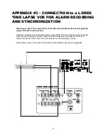
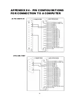
Please refer to Appendices #2-4 for diagrams of Alarm Block connections
GND –
the Ground connection of the Alarm Block.
1.
2.
3.
4.
5.
6.
7.
8.
9.
10
11.
12.
BACK PANEL


