
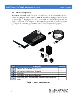


WSDA
®
-Base-104
®
USB Base Station
User Manual
System Operational Overview
17
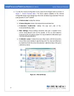
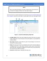
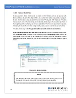
2. To enter the channel configuration menu, select the Configure button as shown in
Figure 7 - Node Channels Menu
. The menu options available on the channel
configuration page varies depending on the node and sensor type selected. This is an
example with a V-Link
®
-LXRS
®
.
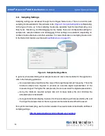
a.
Channel Label:
names the channel
b.
Channel diagram:
shows channel electronics and data flow
c.
Conversion
Coefficients:
defines
the type and
units of the
measurement being made
d.
PGA Settings:
These settings determine what gain is applied to the
sensor measurement and set the position of the no- load baseline
measurement for the sensor signal. It is only available for differential input
channels with gain amplifiers.
e.
Calibration values:
includes the slope, offset, scale, and formula used to
convert the sensor reading to engineering units. The slope and offset can
be determined from the sensor manufacturer calibration data or through a
calibration process.
Figure 8 - Channel Setup


