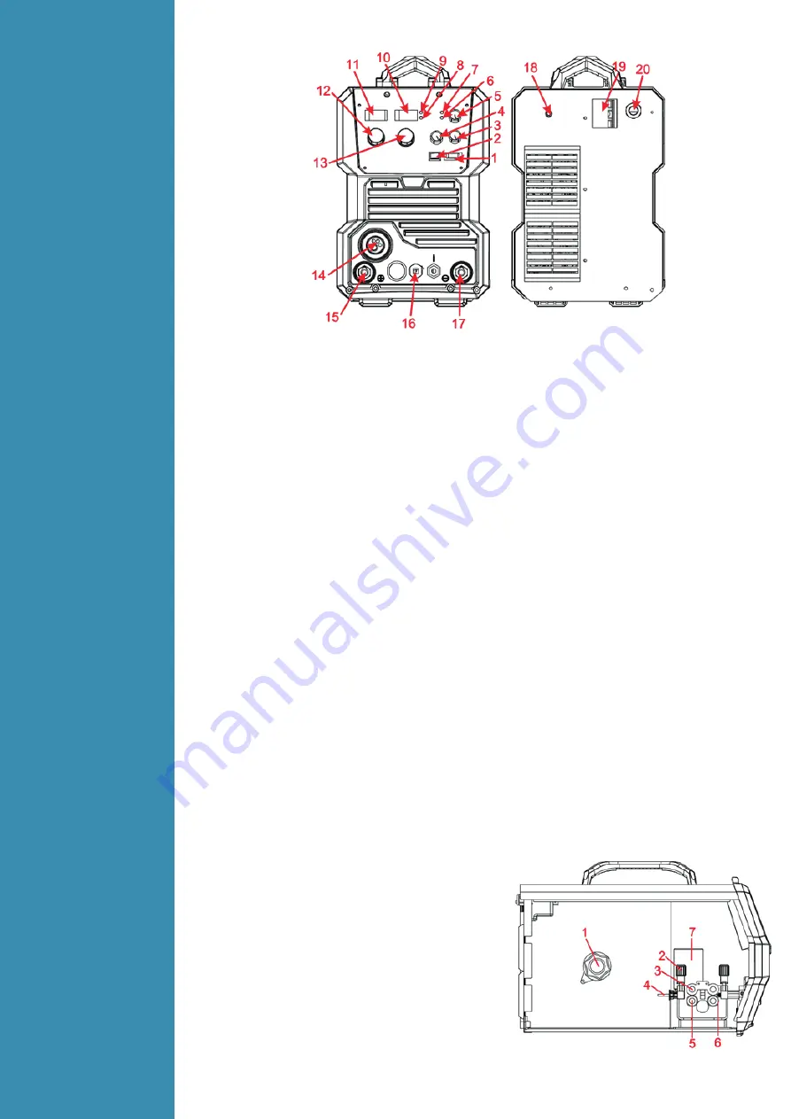
LOKERMANN GRAND MIG 315 COMPACT Скачать руководство пользователя страница 8

Operation
4.1

Layout for 

the front 

and rear 

panel

1.     Manual inch wire switch & test gas switch: left for manual inch wire and right for test gas.

2.     Choose welding mode switch: left for 2T welding mode and right for 4T welding mode.

3.     Burn back knob

4.     Wave control knob: Controls arc characteristics, Determines the rate at which the amperage rises

        when a short circuit is produced.

5.     Soft arc knob: to select the speed of the wire at the start, before arc igniction.

6.     Alarm Led: When the welder is over voltage, less voltage, over current or over heated, the alarm 

        pilot lamp will be on.

7.     Power Led: Power led is lighted when switch on the machine.

8.     Current LED: When the current LED is on, it display the actual output welding current.

9.     Wire speed LED: You can use current setting knob to set the wire speed when the wire speed 

        LED is on.

10.   Current display: Welding Current display when machine is working, Set current display before 

        welding. Unit

A.

11.   Voltage display: Welding voltage display when machine is working, Set voltage display when MIG

        mode before welding. Unit

V.

12.   Welding volt knob: Set the welding volt

13.   Welding current/wire speed knob: Set the welding current/wire speed. 

14.   MIG GUN Connect.

15.   Output positive

16.   MIG Torch Polarity Change Power Connection: Connect to”+”, the MIG gun connecter will be

        “+”, connect to “-”, the MIG gun connecter will be “-”;

17.   Output negative

18.   Shield gas input joint: To connect one head of the gas hose while the other head of which is 

        connected to argon gas cylinder. 

19.   On/off switch: Control the power supply on and off.

20.   Power source input cable: To connect power source.

4.2 

Wire 

Feeder of 

welding 

machine

1.     Spool holder.

2.     Wire feed tension adjustment (2x). 

3.     Wire feed tension arm (2x). 

4.     Wire feeder inlet guide.

5.     Drive roller retainer (2x).

6.     Wire drive roller (2x).

7.     Wire feed motor.

Содержание GRAND MIG 315 COMPACT

Страница 1: ...IMPORTANT Read this OPERATOR MANUAL together with PRESCRIPTION AND COMPLIANCE MANUAL before to use this equipment In case of loss one of two parts contact immediately your dealer Allow the operator t...

Страница 2: ...4 1 Layout for the front and rear panel 4 2 Wire Feeder of welding machine 4 3 Welding operation 4 3 1 Wire Feed Roller Selection 4 3 2 Wire Installation and Set Up Guide 4 3 3 MIG Torch Liner Instal...

Страница 3: ...ring of the public supply system Consideration should be given to shielding the supply cable of permanently installed arc welding equipment in metallic conduit or equivalent Shielding should be electr...

Страница 4: ...5 COMPACT Features 1 Digital control system real time display the welding parameters 2 High performance power source MIG MAG 3 Waveform control stable welding arc 4 IGBT technology low power consumpti...

Страница 5: ...The relation between the rated loading voltage and welding current 3 Installation and Adjustment 3 1 Parameters Models Parameters GRAND MIG 315 COMPACT Input Voltage V 3 380 400 440 10 Frequency HZ 5...

Страница 6: ...ut current or the duty cycle should be reduced 3 3 Equipment Connection 1 Insert the earth cable plug into the negative socket on the front of the machine and tighten it 2 Plug the welding torch into...

Страница 7: ...ne end of the guide Tighten the wire guide in place with the mounting nut Cut the wire guide 2mm from the mounting nut and file the sharp edges of the cut round Reattach the gun in place and tighten t...

Страница 8: ...en the wire speed LED is on 10 Current display Welding Current display when machine is working Set current display before welding Unit A 11 Voltage display Welding voltage display when machine is work...

Страница 9: ...t screw the contact tip into the tip holder of the torch head and nip it up tightly 7 Fit the gas nozzle to the torch head 8 Carefully open the gas cylinder valve and set the required gas flow rate 9...

Страница 10: ...bend easily and is therefore more difficult to feed Soft wires can easily buckle at the wire feeder where the wire is fed into inlet guide tube of the torch The U shaped roller offers more surface ar...

Страница 11: ...rrect drive tension is to bend the end of the wire over hold it about 100mm from your hand and let it run into your hand it should coil round in your hand without stopping and slipping at the drive ro...

Страница 12: ...al diameter clearance Most manufacturers will produce liners sized to match wire diameters and length of welding torch cable and most are colour coded to suit 4 3 5 MIG Welding Definition of MIG Weldi...

Страница 13: ...r travel speeds providing a flatter weld profile with light penetration useful for welding thin materials The welds are wider and flatter allowing for minimal clean up grinding time Perpendicular Tech...

Страница 14: ...d pool produce spatter and over heat the contact tip Too long stick out will cause an unstable arc lack of penetration lack of fusion and increase spatter Travel Speed Travel speed is the rate that th...

Страница 15: ...producing a weld deposit of good quality Gas selection The purpose of the gas in the MIG process is to protect shield the wire the arc and the molten weld metal from the atmosphere Most metals when he...

Страница 16: ...g MM Gas flow rate L MIN Butt joint 1 6 1 0 80 100 19 21 40 50 12 15 10 15 2 0 1 0 90 100 19 21 40 50 13 16 13 15 3 2 1 2 150 170 22 25 40 50 14 17 15 17 4 5 1 2 150 180 24 26 30 40 14 17 15 17 6 0 1...

Страница 17: ...arc in unprotected eyes Ensure good ventilation of the machine to improve Duty Cycle Turn off the engine when the operation finished for energy consumption efficiency When power switch shuts off prote...

Страница 18: ...ches in the front and at the back of arc welding machine are flexible and put correctly in place If any knob has not been put correctly in place please correct If you can t correct or fix the knob ple...

Страница 19: ...protection always on Welding machine E10 Phase loss Yellow lamp thermal protection always on E12 No gas Red lamp always on E13 Under voltage Yellow lamp thermal protection always on E14 Over voltage...

Страница 20: ...LOKERMANN Srl Via Produzione 16 18 37044 Cologna Veneta VR Italy Tel 39 0442 1722469 lokermann lokermann eu www lokermann eu...

Отзывы: