50
30
30
protection against
flying sparks
800
90°
Biegemaul 30
Strahlungsbereich
Rückwand
Aqua
Insert
OBERFLÄCHE
SONSTIGE
ZEICHNUNGSINFOS:
ABMESSUNGEN IN
MILLIMETER
TOLERANZEN:
LINEAR: DIN ISO 2768 T1 -m-
WINKEL: DIN ISO 2768 T2 -H-
BENENNUNG
1:20
FORMAT ZEICHNUNGSNUMMER
A4
REV.
MATERIAL
NAME
DATUM
GEZEICHN.
GEPRÜFT
FREIGABE
BLATT 1 VON 2
LOHBERGER
GEWICHT: kg
FÜR DIESE ZEICHNUNG
BEHALNTEN WIR UNS
ALLE RECHTE VOR,
SIE DARF OHNE UNSERE
VORHERIGE SCHRIFTLICHE
ZUSTIMMUNG WEDER
VERVIELFÄLTIGT NOCH
SONST WIE BENÜTZT, NOCH
DRITTEN ZUGÄNGLICH
GEMACHT WERDEN!
ARTIKELNUMMER
PRG.NR.
ZUSCHNITTMAß
FERTIGMAß
ROHTEILNUMMER
Heiz + Kochgeräte
Technologie GmbH
BESCHREIBUNG
MAßST.:
B:\Entwicklung HH\-- Laufende Projekte\Heizeinsatz Fa. Plewa\Prüfungen\TÜV\Dokumente und Zeichnungen für Aqua Insert Zeichnungs
prüfung\Zeichnungen-Bilder für Bedienungsanleitung\Baugruppe Sicherheitsabstand
mm
Seite 10
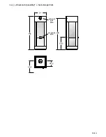
11. Safety clearances
11. Safety clearances
Figure 10
Figure 11
the following safety clearances to combustible items (movable wooden walls,
furniture, furnishing fabric, etc.) must be maintained:
Within the area of heat radiation
(Figure 10)
, the minimum clearance of 800 mm
from the front of the combustion chamber opening to combustible components
must be maintained.
Floor pad as a protection against flying sparks
ith combustible floors (timber flooring, synthetic materials, fitted carpet, etc.),
the use of a floor pad made of safety glass or similar non-combustible materi-
als is recommended
according to fire protection laws, the minimum size (measurements in cm) for
this pad as shown in
Figure 11
must be observed.
Minimum distance flue pipe to ceiling:_______________________24 cm
Minimum clearance appliance body to combustible materials
rear:____________________________________________15 cm
sides:___________________________________________30 cm
Minimum distance flue pipe to ceiling:_______________________24 cm
Minimum clearance appliance body to combustible materials
rear:____________________________________________15 cm
sides:___________________________________________30 cm
12. Requirements for the room where the appliance is situated
12. Requirements for the room where the appliance is situated
Load-bearing capacity of the floor
prior to installing the appliance, make sure that the substructure of the floor
is suitable for the weight of the appliance. ensure a level and vibration-free
positioning of the appliance.
room temperature and ambient temperature / humidity
the appliance can be operated in dwellings with normal air humidity and room
temperatures of + 5 °C to + 20 °C.
For room temperatures below 5 °C, the water circuit must have an appropriate anti-
freeze.
the appliance is not protected against water spray and must not be installed in wet
rooms.
thermo
Insert
100
reAr WALL


