9
5.
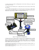
Connect connectors X2 and X3 of folding handle rod with cable of off-line power supply unit
(cable marking «Cab. BP»);
6.
Connect connectors X1 BAPP and X1 of folding handle rod by antenna cable unit (cable marking
«Cab. BAPP»);
7.
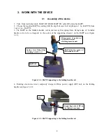
Fix the BUOI on the folding handle rod. For that turn clock-wise the fixing arm of BOUI and fix
it in this position, insert guiding connector, to the corresponding parts of the guide supporting element
SSHR and then return a fixing arm of BOUI in a starting position (figure 3.1.3);
Figure 3.1.3. Support BUOI on folding handle rod.
8.
Rotating clock-wise (if looking clockwise from the side of the supporting element of BUOI)
release the socket joint fixing the location of a folding handle rod (figure 3.1.3) and pulling the
telescopic of a folding handle rod up to the required value, adjust the length of a f.b.h. (regarding the
standing height of a person), then rotating counterclockwise (if looking from the side of a supporting
element of BOUI) tighten the fixing socket joint;
9.
Releasing the screw which fixes the turn of BUOI movement, adjust the turn angle of BUOI in a
relation to a handle rod (figure 3.1.3);
10.
On releasing the srew fixing the turn angle of BAPP, adjust the angle of slope of antenna unit in
relation to a handle rod (figure 3.1.1).
BUOI, front view
The «start-stop»button for the
start operating control process
and for finish cargo scanning
Supporting element for
BUOI on folding
handle rod
, font view
Connector guiding for
connection to the folding
handle rod
BUOI, back view
Connector for connection
BUOI to the folding
handle rod
Bolt fixing corner
of turning BUOI
Fixing socket joint
BUOI, back view
.
Set of a guide supporting
element
Fixing arm BUOI


