
5 -
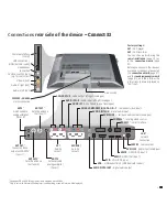
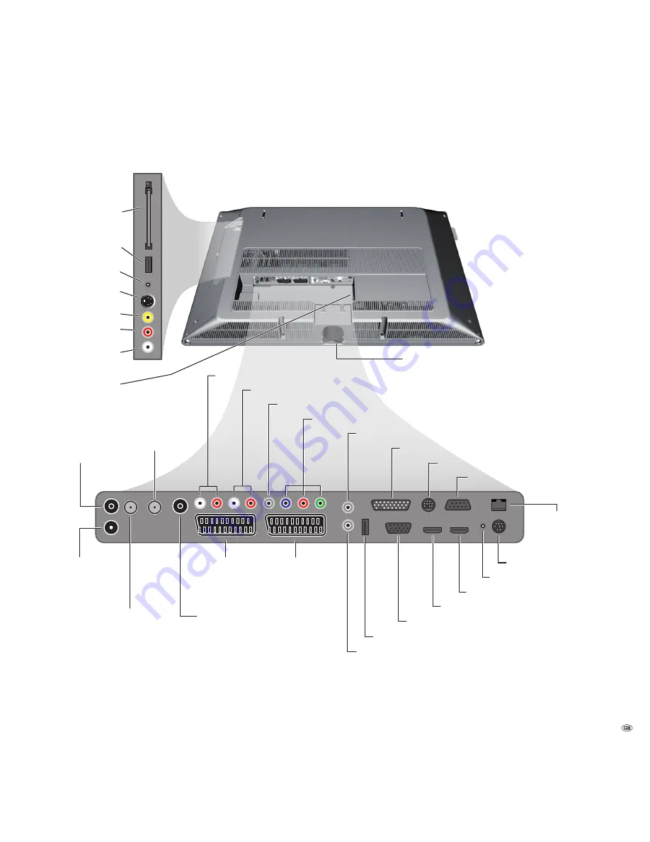
ANT OUT
(1
Connect antenna
output with ANT-TV
(tuner 1)
ANT-TV
Antenna/cable
analogue/digital
(Tuner 1)
mains switch
CONTROL
(1
- rotating stand control
RS-232C
(1
- serial interface
AUDIO IN1 L/R
- audio input left/right (analogue)
AUDIO OUT L/R
- audio output left right (analogue)
ANT SAT2
(1
Satellite antenna
(Sat tuner 2)
ANT2
(1
Antenna/cable
analogue/digital
(Tuner 2)
AV1
Euro-AV
socket 1
AV2 (RGB)
Euro-AV
socket 2
220-240V~ 50/60Hz
mains connection
SERVICE
- service socket
PC IN
- VGA-/XGA input
HDMI2
- HDMI (DVI) input 2
AUDIO DIGITAL IN
- digital audio input
USB
(1
- USB connection 2 (USB stick/card reader)
SD/HD-COMPONENT IN Cb/Pb–Cr/Pr–Y
- component video inputs
Headphones
connection
Common Interface
(CI-Slot)
S-VHS connection (AVS)
(e.g. for camcorder)
Video in (AVS)
Audio in right (AVS)
Audio in left (AVS)
AUDIO IN1 C
- centre audio input (analogue)
AUDIO LINK
(1
- surround audio outputs (analogue)
HDMI1
- HDMI (DVI) input 1
USB connection 1
(USB stick/card reader)
ANT SAT
(1
Satellite antenna
(Sat tuner 1)
AUDIO IN2
- audio input (analogue)
AUDIO DIGITAL OUT
- digital audio output
LAN
(2
-
network
connection
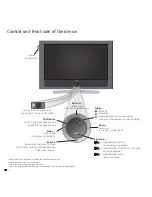
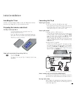
Connections re�r side of the device – Connect ��
re�r side of the device – Connect ��
– Connect ��
(1
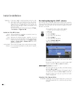
See pages 58 and 59 for equipment and upgrade possibilities.
(2
Only in sets with Network Mediaplayer (see operating manual Network Mediaplayer).
Factory settings:
AV1:
DVD player
AV2:
DVD recorder
You can change this during the
initial installation
(page 12) or
in the
connection wizard
(page
37).
Before you connect other devices
or make any changes, please start
the
connection wizard
(page 37)
and the
sound components wizard
(page 41), and then follow the
instructions that are displayed on
the TV set.
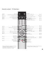
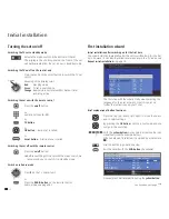
C O N N E C T
Connectivity
C
DR+
:
Station up
in the menu: to the right
On/Off button
:
Switch on from the standby mode
Switch off to the standby mode
Button –
:
Station down
in the menu: to the left
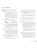
Display
:
= Standby
= Operation
= Operation without on-screen display
(Radio, EPG data capture or timer recording)
Button R
:
Radio on/off
(1
(back to TV mode)
Switch on the radio from the standby mode
in the menu: down
Button M
:
Call the menu
in the menu: up/down
DR+
= Digital Recorder inactive
(no recording, no playback)
DR+
= Digital Recorder active (offset TV viewing
or archive playback)
DR+
= Digital Recorder active
(archive recording)
Display DR+
:
(2
The mains switch is located on
the bottom of the set in the middle
Display
Connectivity
(3