8
Units with anti-tipping rollers should be adjusted to pro-
vide 1/8” maximum gap between the bottom of the
beam and the roller. Run the trolley the length of the
beam to check for tight places. Readjust if needed.
On geared trolleys, the bottom of the hand chain loop is
normally located two feet (0.6M) above the floor. If it is
desired to change this, find the unwelded link and open
it by spreading with a chisel or twist one end with a
wrench while holding the other end in a vise or another
wrench. Remove an even number of links (2,4,6, etc.) as
necessary to shorten the chain or add an even number of
links to lengthen the chain (when lengthening the chain,
another open link will be required and this can be made
from a welded link by cutting through weld with a hack-
saw). Make certain that the chain is not twisted–then re-
install and close open links.
NOTE:
AFTER THE UNIT IS CONNECTED TO THE
AIR SUPPLY SYSTEM (SEE BELOW), SUS
PEND A CAPACITY LOAD FROM THE HOIST
AND OPERATE THE TROLLEY OVER THE
ENTIRE LENGTH OF THE RUNWAY OR MONO
RAIL SYSTEM TO BE SURE THAT THE ADJUST
MENTS AND OPERATION IS SATISFACTORY.
ON SYSTEMS WITH CURVES,THE EDGES OF
THE RAIL AT THE CURVED SECTIONS SHOULD
BE KEPT LIGHTLY LUBRICATED WITH GREASE.
INSTALLING MUFFLER
Install the 3” long 1 1/4” NPT pipe nipple through the
hole in the motor end cover and thread it into the valve
exhaust port. Install the 1 1/4” NPT pipe elbow onto the
end of the pipe nipple. Tighten the elbow until it faces
downward. Install the muffler into the elbow and tight-
en.
!
WARNING
An excessively worn beam flange may fail and allow
the trolley to fall from the beam.
TO AVOID INJURY:
Periodically inspect the beam flange for wear. Replace
beam if flange is worn.
INSTALLING BREATHER
After the hook suspension is assembled to the hoist or after the
hoist and trolley are mounted on the beam, remove the upper
plug from the main housing (652-110) and install the breather
(inside information envelope). Failure to install the breather
could damage oil seals and thus cause oil leaks.
AIR SUPPLY SYSTEM
Connect the hoist to a filtered and lubricated air source
using a 1” (25.4 mm.) I.D. hose (see Figure 3). Do not use
smaller diameter hose, since it will restrict air flow and
reduce hoist performance. If the hoist is suspended from a
trolley, provide sufficient hose to reach from the source to
the farthest point of trolley travel. Hose Trolleys are rec-
ommended to keep the hose up and out of the way.
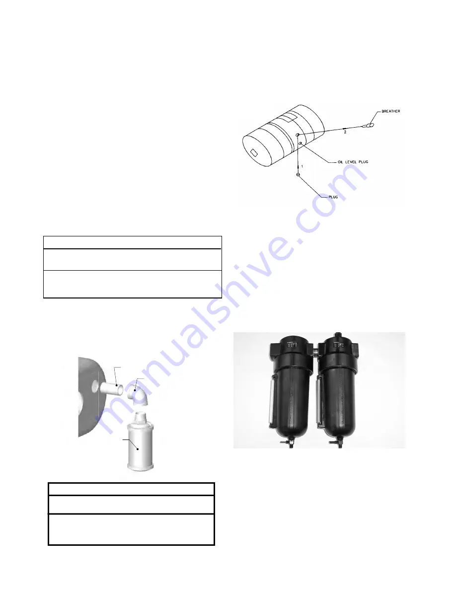
A filter and lubricator (see Figure 3)
must
be installed
between the air source and the air hose leading to the
hoist. These keep the air flowing free from dirt and add
lubricant to the air so internal parts of the motor are con-
stantly lubricated. Use a good grade of air powered tool
oil or SAE 10W machine oil. Such oil can be obtained from
CM
®
, Coffing, or Budgit.
The recommended operating air pressure for the hoist is
90 psig. When line pressure exceeds 100 psig (at the hoist
when it is lifting rated load), it is recommended that a
pressure regulator be provided in the air supply line to
keep the pressure at 90 psig. Although there is a wide
range of pressures within which the hoist will operate,
motor efficiency decreases as the air pressure drops.
Excessive moisture in the air line may cause rust or ice to
form in the muffler when air expands as it passes through
the motor. Install a moisture separator in the air line and
an after cooler between compressor and air receiver to
help prevent moisture problems.
INSTALL
BREATHER
Figure 3. Filter and Lubricator Unit
!
WARNING
Operating hoist without muffler can cause hearing
loss.
TO AVOID INJURY:
To avoid injury, only operate hoist with muffler
securely attached.


