7
4. On geared trolleys, make sure the handwheel
is on the loose end/chain container side of the hoist.
On motor driven trolleys make sure the motor is
located on the loose end/chain container side of the
hoist.
INSTALLING TROLLEY SUSPENDED HOIST ON BEAM
Stops must be positioned to contact the trolley side
frames and not exert impact force on the hoist.
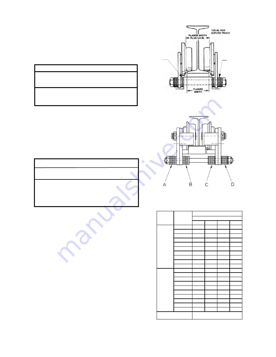
Trolleys are mounted on the hoist prior to shipment
and side frames are positioned for the nominal beam
flange specified on the order. However, due to varia-
tions in beam flange widths, actual beam flange width
should be measured to determine the exact distribu-
tion of the spacer washers. See Mounting Trolley On
Hoist Section.
!
WARNING
TO AVOID INJURY:
Install rail stops at each end of the beam on which
the trolley is to operate.
!
WARNING
If washer spacing recommendations are not followed,
trolley may fall from beam.
TO AVOID INJURY:
Measure the actual beam flange on which the trolley
is to operate and use Table 2 to determine the
arrangement of the spacer washers for that flange
width.
NOTE: USE OF OTHER THAN SUPPLIED SPACER WASHERS
MAY CAUSE IMPROPER TRACKWHEEL SPACING.
Table 2. Trolley Spacer Washer Arrangement
Plain and Geared
Figure 2.
Figure 1.
QUANTITY OF
OUTSIDE WASHERS
SHOULD BE EQUAL
-BOTH SIDES
QUANTITY OF
INSIDE WASHERS
SHOULD BE EQUAL
-BOTH SIDES
Operating the trolley on a beam that has no rail
stops may allow the trolley to fall off the end of the
beam.
Before installing geared or motor driven trolleys (2 ton
only) on the beam, lubricate the trackwheel gears and
pinion with Texaco Novatex #2 or equivalent heavy cup
grease.
On open end beams, remove rail stops, lift hoist/trolley
into position and slide the hoist/trolley assembly onto
beam flange. Reinstall the rail stops.
On closed end beams, loosen the suspension bolt nuts
on one side of trolley and slide one side frame out far
enough to clear the beam flange. Lift hoist/trolley
assembly up so that trackwheels are riding on beam
flange. Draw side frames together by tightening the
suspension bolt nuts snugly.
Be sure to install cotter pins through slotted nuts and
hole in suspension bolts and spread legs of cotter pins
to secure on 2 ton plain and geared units. For 2 ton
motor driven trolley and 3 thru 7 1/2 ton units, be sure
lockwashers are positioned properly on the suspension
pins and completely tightened.
FLANGE
WIDTH
IN.(mm)
2 Ton
No. of Washers
A
B
C
D
Standard
Trolleys
3 3/8 (82.7)
13
0
0
13
3 5/8 (92.0)
11
2
2
11
3 7/8 (98.4)
10
3
4
9
4 (101.6)
9
4
4
9
4 1/8 (104.7)
8
5
5
8
4 5/8 (117.4)
5
8
8
5
5 (127.0)
3
10
10
3
5 1/8 (130.1)
3
10
11
2
5 1/4 (133.3)
2
11
12
1
5 1/2 (139.7)
0
13
13
0
Special
Trolleys
5 5/8 (142.9)
12
1
1
12
6 (1252.4)
10
3
3
10
6 1/4 (158.7)
9
4
5
8
6 3/8 (161.9)
8
5
6
7
7 (177.8)
4
9
9
4
7 1/8 (181.0)
3
10
10
3
7 1/4 (184.1)
3
10
11
2
7 3/8 (187.3)
2
11
12
1
7 1/2 (190.5
1
12
12
1
7 5/8 (193.7)
0
13
13
0
*Minimum Beam
Radius ft. (M)
4’-0” (1.22)
*
Dimension applies to minimum S-beam and will
vary with larger s-beams.


