background image

3 (9)

Pipe installation

Circulation pump

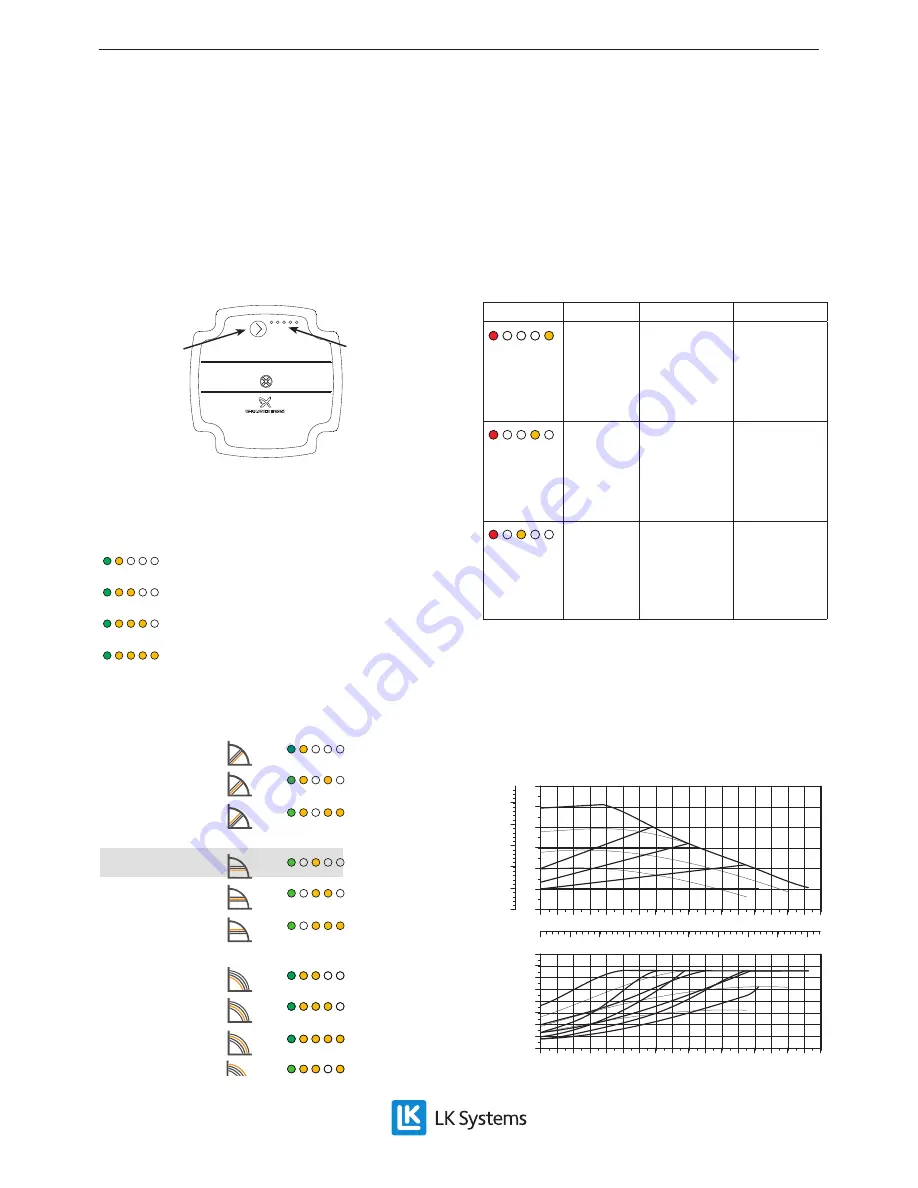
Delivery setting: Constant pressure curve 1. 

If parts of the heating system do not get hot, 

this can be changed to Constant pressure curve 

2. Selecting a higher curve increases energy con-

sumption and operating costs.

Push but-

ton

LEDs

In operating mode, the first LED lights up green, 

and between one and four LEDs light up yellow. 

The yellow LEDs indicate the operating capacity 

of the pump.

0 - 25 %

25 - 50 %

50 - 75 %

75 - 100 %

Pressing the button displays the pump setting for 

2 sec before the pump returns to normal display.

PROP. PRESSURE: CURVE 1

PROP. PRESSURE: CURVE 2

PROP. PRESSURE: CURVE 3

CONST. PRESSURE: CURVE 1

CONST. PRESSURE: CURVE 2

CONST. PRESSURE: CURVE 3

CONST. CURVE: KURVA 1

CONST. CURVE: KURVA 2

CONST. CURVE: KURVA 3

CONST. CURVE: KURVA 4

If the button is depressed for 2 sec, the pump 

switches to setup mode and the LEDs flash. In 

setup mode, any one of 10 curves can be selected 

by turning the button. When the button has been 

released for 10 sec, the pump returns to operat-

ing mode, the LEDs stop flashing and the selected 

curve becomes active.

A lit red LED indicates an alarm or warning.

Indication

Fault

Status

Measure

Red 

fourth 

yellow

Motor 

blocked

Pump tries 

to restart 

at 1.5 sec 

intervals

Release 

motor/

impeller or 

wait

Red 

third yel-

low

Low volt-

age

Warning 

only, pump 

continues to 

operate

Check volt-

age to pump

Red 

second 

yellow

Electrical 

fault

Pump 

stopped

Check volt-

age/replace 

pump

A button lock prevents accidental adjustments to 

the pump settings. The button can be locked/un-

locked by depressing the button for 10 seconds. 

After 10 seconds, all the LEDs will flash quickly 

to indicate that the lock is locked/unlocked.

Pump capacity

0

1

2

3

4

0.0 0.2 0.4 0.6 0.8 1.0 1.2 1.4 1.6 1.8 2.0 2.2 2.4 2.6 2.8

Q [m³/h]

5

[m]

H

0

10

20

30

40

50

[kPa]

p

0.0

0.1

0.2

0.3

0.4

0.5

0.6

0.7

0.8

Q [l/s]

0

5

10

15

20

0.0 0.2 0.4 0.6 0.8 1.0 1.2 1.4 1.6 1.8 2.0 2.2 2.4 2.6 2.8

Q [m³/h]

25

30

35

[W]

P1

EN.33.C.111.1804

Содержание Electric Boiler-4.5

Страница 1: ...wall mounted elec tric boiler intended primarily for low temperature heating systems e g under floor heating LK Electric Boiler 4 5 kW is delivered as a complete unit The boiler is ready for use once the water and electricity are connected The boiler includes Thermostat Overheating maximum safe temperature protection Indication power on and triggered overhea ting maximum safe temperature protectio...

Страница 2: ...stment valve should be open by at least half a revolution 1 2 1 Isolation valve supply and return 2 By pass valve accessible after the protective plug has been unscrewed Installation system outline Below is a system outline Units should always be installed according to regulations and standards 4 1 2 3 1 LK Electric Boiler 4 5 2 Filling valve Drain valve 3 Manifolds under floor heating 4 Under flo...

Страница 3: ...de any one of 10 curves can be selected by turning the button When the button has been released for 10 sec the pump returns to operat ing mode the LEDs stop flashing and the selected curve becomes active A lit red LED indicates an alarm or warning Indication Fault Status Measure Red fourth yellow Motor blocked Pump tries to restart at 1 5 sec intervals Release motor impeller or wait Red third yel ...

Страница 4: ...ied out under the supervision of an authorized installer Electric installation Electric installation should be carried out in accor dance with the applicable regulations under the supervision of an authorized electrician The boiler must not be connected to the electrical supply before it is filled with water The boiler should be preceded by all pole circuit switches The ambient temperature must no...

Страница 5: ...capacitor 5 Circulation pump 6 Overheating maximum safe temperature protection 7 Thermostat 8 Electric cartridge 9 Control switches 10 Alarm indication overheating maximum safe temperature protection triggered 11 On off indicating light goes on when vol tage is supplied to the boiler 12 Contacts External switching room thermostat The boiler can be blocked by external equipment e g room thermostat ...

Страница 6: ...perature protection triggered Inspect together with installer after the instal lation that the unit is in a satisfactory condition Have the installer demonstrate how the unit works and should be handled The boiler and the heating system must be filled with water before the circuit switch is set to on The boiler cover should be assembled during ope ration Note Monitor the amount of water in the ves...

Страница 7: ...ox 35 40 C and for wooden joists approx 40 45 C The desired temperature varies according to the time of year Safety valve The safety valve should be exercised regularly to maintain the safety function Overheating maximum safe temperature protection The overheating maximum safe temperature pro tection on the boiler is triggered when the boiler temperature exceeds 80 The protection is restored on th...

Страница 8: ... the boiler temperature falls below 65 C push the button hard for reset No or insufficient heat Thermostatic valves on the heating system or boiler thermostat set at too low temperature Inspect and adjust Faulty adjustment of bypass valve Inspect and adjust Group fuses for boiler are triggered The electric cartridge is broken Inspect the electric cartridge by testing it in isolation Measure betwee...

Страница 9: ...iler no Cogeneration space heater no Combination heater no Rated heat output Prated 5 kW Useful heat output at rated heat output P4 4 5 kW Energy class D Seasonal space heating energy efficiency boiler boiler with UTK ηs ηs 36 38 Useful efficiency η4 39 7 Auxiliary electricity consumption in stand by mode PSB 0 019 kW Standby heat loss Pstby 0 037 kW Material recycling After dismantling the boiler...

Отзывы: