1
18
If you never read manuals and prefer to dive in blind please at least read
the following before starting.
After powering up the Multi Z PIP wait at least one minute before changing
any switch settings. The unit has to stabilize its large reservoir capacitor
and zero voltage sources. If you do not wait, loud pops will occur when
changing settings. These pops could be damaging to other equipment.
The Multi Z PIP has many options, be aware of how the PIP is configured.
If you chose some of the custom options read the jumper settings part
of this manual carefully before moving the jumpers and of course do it
with the power off.
Plug your speaker output into the Multi Z PIP only after selecting the
speaker in, then do not change the input select while speaker level is feed-
ing the Multi Z PIP, (otherwise damage to the internal electronics could
result from the excess level being fed into it). When using the speaker in
mode, keep in mind this is not a power soak. Many amplifiers require a
load and could be damaged when not using either a power soak or speaker
connected to its output. Do not plug the speaker out of the amplifier
into the Multi Z PIP and then plug the speaker through the Multi Z PIP
Instrument thru. This will send excessive current through the internal
traces of the Multi Z PIP and burn the traces up.
There you have it, but please read on for more information and tips that
should help the inexperienced and experienced engineer alike in obtain-
ing the highest performance out of the Little Labs Multi Z Professional
Instrument Preamplifier.
read this before using the
little labs multi z pip
1. With a 1/16” Allen hex remove the two rear panel capscrews and the
2 xlr cap screws.
2. The rear panel and the plastic frame should come right off. A service
loop is provided so keep the power connector attsched.
3. Slide the black textured steel cover carefully off of the base extru-
sion.
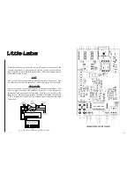
4. This will expose the insides to your leering eyes. Nicely made eh.
Stop here if you just need to change jumper positions.
5. If you need access to under the circuit board use a 1/16” Allen hex to
remove the front screened panel screws. The circuit board should now
easily slide out from the base.
6. Unless you have to replace the pad or switch assembly, I do not
recommend removing the front utility (not screened) panel. If you
must, noting which knob went where, gently but firmly pull off the two
knobs.
7. Use a 1/2” nut driver to remove the front phone jack nut.
8. Use a 7/16” nut driver to remove pad assembly nut.
9. Slide out utility panel and plastic frame so the switch is still at-
tached, and then remove spacer washers from phone jack and pad
assembly. Do not lose these.
10. With a 14mm nut driver or crescent wrench, carefully remove
switch nut, remove utility panel, sliding out the leds then remove spac-
DISASSEMBLY

