39
GAMMA SERIES ENGINES OpERATORS' hANdbOOk
window and No.1 piston in the compression stroke (both valves fully closed).
3. Check and adjust clearance as specified.
4. Repeat the procedure for the remaining valves following the firing order
(3 cylinder engines have firing order 1 - 2 - 3).
5. Replace the rocker cover ensuring that the rocker cover gasket is in good
condition and is correctly positioned.
5.13.2 four Cylinder Engines
The sequence of valves from number 1 cylinder is shown in the table below:
Number 1 cylinder is at the front of the engine (fan and gear end).
VALVe POSITIONS
Cylinder and Valve Number
1
2
3
4
1
2
3
4
5
6
7
8
Valve: I=Inlet; E=Exhaust
I
E
E
I
I
E
E
I
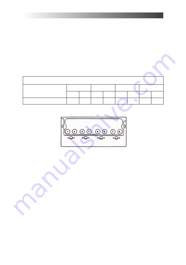
The valve positions are shown in
Figure 5.13.2
.
30
GAMMA SERIES ENGINES OPERATORS' HANDBOOK
removed for service
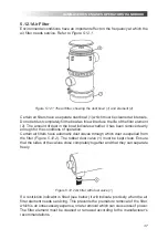
After a clean element has been fitted,
press the rubber bottom (3) of the
button (4) of the restriction indicator to
reset the red warning indicator.
Figure 5.12.3 Restriction indicator: (1)
warning light; (2) clear panel; (3) rubber
base; (4) button.
5.13 CHECKING VALVE
CLEARANCES
The valve clearances are checked
between the top of the valve stem and
the rocker lever
(Figure 5.13)
with the
engine hot or cold.
Figure 5.13 Checking valve clearances.
The correct clearances are 0.20mm
(0.008 in) for inlet valves and 0.45mm
(0.018 in) for exhaust valves.
Note:
Number 1 cylinder is at the front of the
engine.
5.13.1 Three Cylinder Engines
1.Remove the cover plate in the
window of the flywheel housing
2. Rotate the crankshaft until the T.D.C.
line on the flywheel is in the centre
of the window and No.1 piston in the
compression stroke (both valves fully
closed).
3.Check and adjust clearance as
specified.
4.Repeat the procedure for the
remaining valves following the firing
order (3 cylinder engines have firing
order 1 - 2 - 3).
5.Replace the rocker cover ensuring
that the rocker cover gasket is in
good condition and is correctly
positioned.
5.13.2 Four Cylinder Engines
The sequence of valves from number 1
cylinder is shown in the table below:
Number 1 cylinder is at the front of the
engine (fan and gear end).
VALVE POSITIONS
Cylinder and
Valve Number
1
2
3
4
1 2 3 4 5 6 7 8
Valve: I=Inlet;
E=Exhaust
I E E I
I E E I
The valve positions are shown in
Figure
5.13.2.
Figure 5.13.2 The valve positions
(GW4, GWT4)
Figure 5.13.2 The valve positions (GW4, GWT4)
1. Rotate the crankshaft in the normal direction of rotation until the inlet valve
(8) of number 4 cylinder has just opened and the exhaust valve (7) of the
same cylinder has not closed completely. Check the clearances of the valves
(1 and 2) of number 1 cylinder and adjust them, if necessary.
2. Set the valves (3 and 4) of number 2 cylinder as indicated above for number
4 cylinder. Then check and adjust the clearances of the valves (5 and 6) of
number 3 cylinder.
3. Set the valves (1 and 2) of number 1 cylinder. Then check and adjust the
clearances of the valves (7 and 8) of number 4 cylinder.
4. Set the valves (5 and 6) of number 3 cylinder. Then check and adjust the
clearances of the valves (3 and 4) of number 2 cylinder.
Содержание GW3
Страница 59: ...59 ...


